Toyota Venza: Front Passenger Side Door Entry Lock and Unlock Functions do not Operate
DESCRIPTION
When the entry lock and unlock functions do not operate only for the front passenger door, an error in output request codes from the front passenger door or malfunction in the front door outside handle assembly is suspected. If the entry functions for the other doors operate normally, then the communication circuit between the key and door control receiver assembly is functioning normally. In this case, radio wave interference or a malfunction in the request code sending circuit (from the certification ECU (smart key ECU assembly) to the front door outside handle assembly (for driver side)) is suspected.
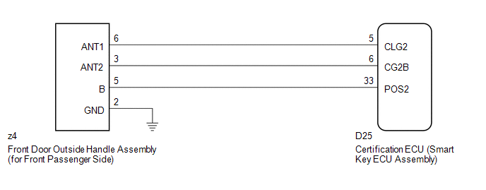
WIRING DIAGRAM
CAUTION / NOTICE / HINT
NOTICE:
- The smart key system (for entry function) uses a multiplex communication
system (LIN communication system) and CAN communication system. Inspect
the communication function by following How to Proceed with Troubleshooting
(See page
.gif) ). Troubleshoot the smart
). Troubleshoot the smart
key system (for entry function) after confirming that the communication system is functioning properly. - Confirm that another key is not in the cabin.
PROCEDURE
|
1. |
CHECK POWER DOOR LOCK OPERATION |
(a) When the door control switch on the master switch assembly is operated, check
that the doors unlock and lock according to switch operation (See page
).
OK:
Door locks operate normally.
| NG | .gif) |
GO TO POWER DOOR LOCK CONTROL SYSTEM (Proceed to Problem Symptoms Table) |
|
.gif)
|
2. |
CHECK WAVE ENVIRONMENT |
|
(a) Bring the key near the front door outside handle assembly (for front passenger side), and perform a front passenger door entry lock and unlock operation check. NOTICE: If the key is brought within 0.2 m (0.656 ft.) of the door outside handle assembly, communication is not possible. HINT:
OK: Entry functions operate normally. |
|
.png)
| OK | |
AFFECTED BY WAVE INTERFERENCE |
|
|
3. |
CHECK HARNESS AND CONNECTOR (CERTIFICATION ECU - FRONT DOOR OUTSIDE HANDLE) |
(a) Disconnect the certification ECU (smart key ECU assembly) connector.
|
(b) Disconnect the front door outside handle assembly (for front passenger side) connector. |
|
(c) Measure the resistance according to the value(s) in the table below.
Standard Resistance:
|
Tester Connection |
Condition |
Specified Condition |
|---|---|---|
|
D25-5 (CLG2) - z4-6 (ANT1) |
Always |
Below 1 Ω |
|
D25-6 (CG2B) - z4-3 (ANT2) |
Always |
Below 1 Ω |
|
D25-33 (POS2) - z4-5 (B) |
Always |
Below 1 Ω |
|
D25-5 (CLG2) - Body ground |
Always |
10 kΩ or higher |
|
D25-6 (CG2B) - Body ground |
Always |
10 kΩ or higher |
|
D25-33 (POS2) - Body ground |
Always |
10 kΩ or higher |
|
z4-6 (ANT1) - Body ground |
Always |
10 kΩ or higher |
|
z4-3 (ANT2) - Body ground |
Always |
10 kΩ or higher |
|
z4-5 (B) - Body ground |
Always |
10 kΩ or higher |
|
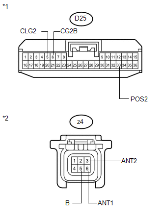
*1 |
Front view of wire harness connector (to Certification ECU (Smart Key ECU Assembly)) |
|
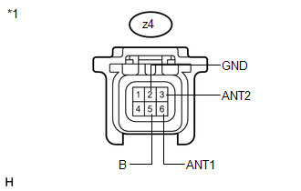
*2 |
Front view of wire harness connector (to Front Door Outside Handle Assembly (for Front Passenger Side)) |
| NG | |
REPAIR OR REPLACE HARNESS OR CONNECTOR |
|
|
4. |
CHECK HARNESS AND CONNECTOR (FRONT DOOR OUTSIDE HANDLE - BODY GROUND) |
|
(a) Measure the resistance according to the value(s) in the table below. Standard Resistance:
|
|
.png)
| NG | |
REPAIR OR REPLACE HARNESS OR CONNECTOR |
|
|
5. |
INSPECT FRONT DOOR OUTSIDE HANDLE ASSEMBLY (DOOR OSCILLATOR, LOCK/UNLOCK SENSOR SIGNAL INPUT) |
(a) Reconnect the certification ECU (smart key ECU assembly) connector.
|
(b) Measure the voltage and check for pulses according to the value(s) in the table below. Standard:
|
|
| NG | |
REPLACE CERTIFICATION ECU (SMART KEY ECU ASSEMBLY) |
|
|
6. |
REPLACE FRONT DOOR OUTSIDE HANDLE ASSEMBLY (for Front Passenger Side) |
(a) Replace the front door outside handle assembly (for front passenger side)
(See page ).
|
|
7. |
CHECK FRONT DOOR OUTSIDE HANDLE ASSEMBLY (for Front Passenger Side) |
(a) Check that the entry functions operate normally (See page
).
OK:
Entry functions operate normally.
| OK | |
END (FRONT DOOR OUTSIDE HANDLE ASSEMBLY WAS DEFECTIVE) |
| NG | |
REPLACE CERTIFICATION ECU (SMART KEY ECU ASSEMBLY) |
 Front Passenger Side Door Entry Unlock Function does not Operate
DESCRIPTION
If the front passenger door entry lock function operates normally, but its entry
unlock function does not, this means that the request code from the front passenger
door is being outp ...
 Driver Side Door Entry Lock Function does not Operate
DESCRIPTION
If the driver door entry unlock function operates normally, but its entry lock
function does not, this means that the request code from the driver door is being
output normally. In th ...
Other materials about Toyota Venza:
Open in Front Floor Electrical Key Oscillator Circuit (B27A5)
DESCRIPTION
The certification ECU (smart key ECU assembly) generates a request signal and
sends it to the indoor electrical key oscillator (for front floor). To detect the
key inside the cabin, the indoor electrical key oscillator (for front floor) create ...
Removal
REMOVAL
CAUTION / NOTICE / HINT
HINT:
Use the same procedure for the RH side and LH side.
The procedure listed below is for the LH side.
PROCEDURE
1. REMOVE REAR POWER WINDOW REGULATOR SWITCH ASSEMBLY WITH REAR DOOR ARMREST
BASE PANEL
...
Precaution
PRECAUTION
HINT:
In the airbag system, the front airbag sensor, door side airbag sensor
and rear airbag sensor are collectively referred to as the airbag sensors.
The steering pad, driver side knee airbag assembly, front passenger
airb ...

0.1732