Toyota Venza: Disassembly
DISASSEMBLY
PROCEDURE
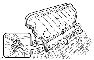
1. REMOVE NO. 1 AIR DUCT SUB-ASSEMBLY
|
(a) Disengage the 4 claws and remove the No. 1 air duct sub-assembly. |
|
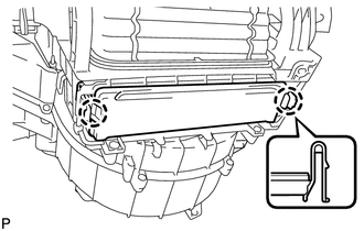
2. REMOVE AIR FILTER COVER PLATE
|
(a) Disengage the 2 claws and remove the air filter cover plate. |
|
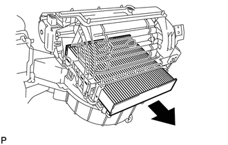
3. REMOVE CLEAN AIR FILTER
|
(a) Remove the clean air filter as shown in the illustration. |
|
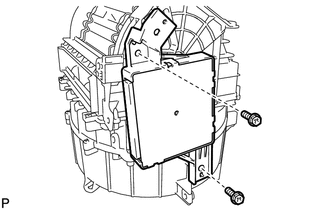
4. REMOVE AIR CONDITIONING AMPLIFIER ASSEMBLY
|
(a) Remove the 2 screws and air conditioning amplifier assembly. |
|
5. REMOVE AIR INLET SERVO MOTOR SUB-ASSEMBLY
|
(a) Remove the screw. |
|
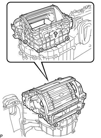
(b) Disengage the 6 claws and remove the blower case.
|
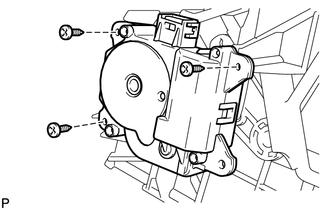
(c) Remove the 3 screws and air inlet servo motor sub-assembly. |
|
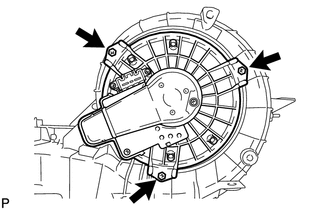
6. REMOVE FRONT BLOWER MOTOR SUB-ASSEMBLY
|
(a) Remove the 3 screws and front blower motor sub-assembly. |
|
 Removal
REMOVAL
PROCEDURE
1. REMOVE AIR CONDITIONING UNIT ASSEMBLY
(See page )
2. REMOVE NO. 1 FINISH PANEL MOUNTING BRACKET
3. REMOVE NO. 2 FINISH PANEL MOUNTING BRACKET
4. REMOVE NO. 3 AIR DUCT ...
 Reassembly
REASSEMBLY
PROCEDURE
1. INSTALL FRONT BLOWER MOTOR SUB-ASSEMBLY
(a) Install the front blower motor sub-assembly with the 3 screws.
2. INST ...
Other materials about Toyota Venza:
One or more Power Seat Motors do not Operate
DESCRIPTION
Signals are input into the position control ECU and switch assembly. The built-in
ECU manages the signals received from the position control ECU and switch assembly,
and operates each motor. If the position control ECU and switch assembly rece ...
Rear Occupant Classification Sensor RH Circuit Malfunction (B1783)
DESCRIPTION
The rear occupant classification sensor RH circuit consists of the occupant classification
ECU and rear occupant classification sensor RH.
DTC B1783 is recorded when a malfunction is detected in the rear occupant classification
sensor RH circ ...
Problem Symptoms Table
PROBLEM SYMPTOMS TABLE
HINT:
Use the table below to help determine the cause of problem symptoms.
If multiple suspected areas are listed, the potential causes of the symptoms
are listed in order of probability in the "Suspected Area" ...

0.1532