Toyota Venza: Parts Location
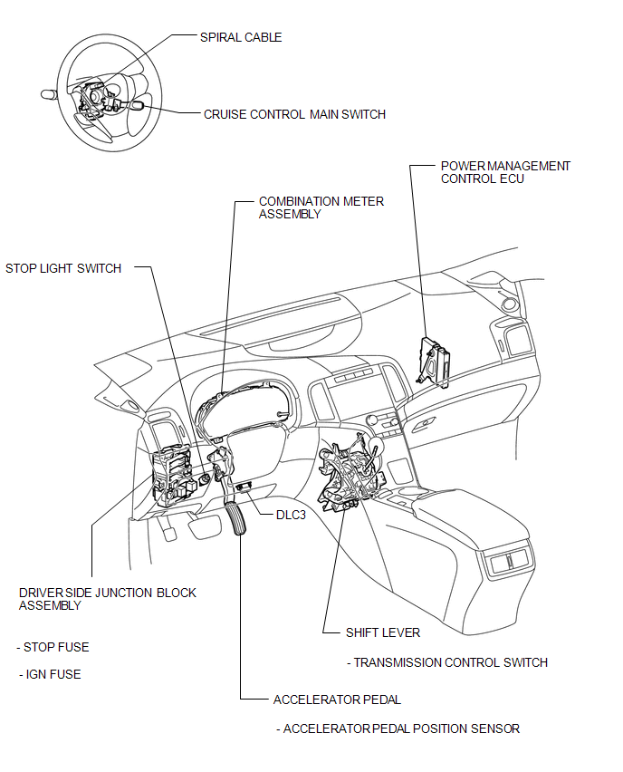
PARTS LOCATION
ILLUSTRATION

ILLUSTRATION
 Precaution
PRECAUTION
NOTICE:
When disconnecting the cable from the negative (-) battery terminal, initialize
the following systems after the cable is reconnected.
System Name
See Proc ...
 System Diagram
SYSTEM DIAGRAM
Communication Table
Sender
Receiver
Signal
Line
ECM
Combination Meter ECU
CRUISE main ...
Other materials about Toyota Venza:
Inspection
INSPECTION
PROCEDURE
1. INSPECT THERMOSTAT
HINT:
The valve opening temperature is inscribed on the thermostat.
(a) Immerse the thermostat in water, and then gradually heat the water.
(b) Check t ...
Transponder Key Amplifier
Components
COMPONENTS
ILLUSTRATION
Removal
REMOVAL
PROCEDURE
1. REMOVE FRONT DOOR SCUFF PLATE
2. REMOVE COWL SIDE TRIM SUB-ASSEMBLY
3. REMOVE LOWER NO. 1 INSTRUMENT PANEL FINISH PANEL
4. REMOVE LOWER STEERING COLUMN COVER
5. REMOVE ...
Front Brake Flexible Hose
Components
COMPONENTS
ILLUSTRATION
Installation
INSTALLATION
CAUTION / NOTICE / HINT
NOTICE:
Because the left and right hoses are not interchangeable, verify the
part number when installing the flexible hoses.
If the hoses are to b ...

0.1289