Toyota Venza: System Description
SYSTEM DESCRIPTION
1. CRUISE CONTROL SYSTEM
This system is controlled by the ECM, and is activated by the throttle position sensor and motor. The ECM controls the following functions: ON-OFF, - SET, + RES, CANCEL, vehicle speed control, motor output control, and shift down control.
- The ECM compares the vehicle speed from the speed sensors with the stored vehicle speed set through the cruise control main switch. The ECM instructs the throttle valve motor of the throttle with motor body assembly to close the valve when the vehicle speed is greater than the stored speed, and instructs it to open the valve when the vehicle speed is less than the stored speed.
- The ECM receives signals such as ON-OFF, - SET, + RES, and CANCEL from the cruise control main switch and executes the command.
- The ECM illuminates the combination meter CRUISE main indicator light
when it receives a cruise control main switch ON signal.
 Text in Illustration
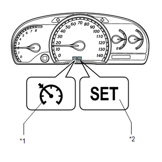
*1
CRUISE Main Indicator Light
*2
SET Indicator Light
- The ECM illuminates the combination meter SET indicator light when constant speed control is set with pushing the cruise control main switch to - SET while driving.
- The ECM cancels cruise control operation when the brake pedal is depressed and the ECM receives a stop light switch signal.
- The ECM cancels cruise control operation when the shift lever is moved from D to N or 3rd, 2nd, or 1st range is selected with the shift lever in S.
2. LIMIT CONTROL
(a) Low speed limit
The lowest possible limit of the speed setting range is set at approximately 40 km/h (25 mph). The cruise control system cannot be set when the vehicle speed is below the low speed limit. Cruise control operation will be automatically canceled but the stored vehicle speed will be retained when the vehicle speed drops below the low speed limit of 40 km/h (25 mph) while the cruise control is in operation.
(b) High speed limit
The highest possible limit of the speed setting range is set at approximately 200 km/h (125 mph). The cruise control system cannot be set when the vehicle speed is over the high speed limit. Also, + RES cannot be used to increase speed over the high speed limit.
3. CRUISE CONTROL OPERATION
The cruise control main switch operates 7 functions: SET, -, TAP-DOWN, RES, +, TAP-UP, and CANCEL. The SET, TAP-DOWN, and - functions, and the RES, TAP-UP, and + functions are operated with the same switch. The cruise control main switch is an automatic return type switch which turns on only while it is being operated in the direction of each arrow and turns off after being released.
(a) SET CONTROL
Vehicle speed is stored and constant speed control is maintained when pushing the cruise control main switch to - SET while driving with the main switch on (the CRUISE main indicator light is on), and the vehicle speed is within the set speed range (between the low and high speed limits).
(b) - CONTROL
When the cruise control main switch is held to - SET while the cruise control system is operating, the ECM sends a "throttle valve opening angle 0°" demand signal to the cruise control system. Then the vehicle speed, when the cruise control main switch is released, is stored and maintained.
HINT:
An actual throttle valve opening angle of 0° is not possible due to the idle speed control, etc.
(c) TAP-DOWN CONTROL
When tapping down the cruise control main switch to - SET (for approximately 0.6 seconds) while the cruise control system is in operation, the stored vehicle speed decreases each time by approximately 1.6 km/h (1 mph). When the cruise control main switch is pushed to - SET and the difference between the driving and stored vehicle speeds is more than 5 km/h (3 mph), the vehicle speed is stored and constant speed control is maintained.
(d) + CONTROL
The throttle valve motor of the throttle with motor body assembly is instructed by the ECM to open the throttle valve when pushing and holding the cruise control main switch to + RES and held while the cruise control system is in operation. When the cruise control main switch is released from + RES, the vehicle speed is stored and the vehicle is controlled at a constant speed.
(e) TAP-UP CONTROL
When tapping up the cruise control main switch to + RES (for approximately 0.6 seconds) while the cruise control system is in operation, the stored vehicle speed increases each time by approximately 1.6 km/h (1 mph). However, when the difference between the driving and the stored vehicle speeds is more than 5 km/h (3 mph), the stored vehicle speed will not be changed.
(f) RES CONTROL
If cruise control operation was canceled with the stop light switch assembly or the CANCEL switch, and if driving speed is within the limit range, pushing the cruise control main switch to + RES restores vehicle speed memorized at the time of cancellation, and maintains constant speed control.
(g) MANUAL CANCEL CONTROL
Performing any of the following cancels the cruise control system while in operation (the stored vehicle speed in the ECM is maintained).
- Depressing the brake pedal
- Moving the shift lever from D to N or 3rd, 2nd, or 1st range is selected with the shift lever in S
- Pulling the cruise control main switch to CANCEL
- Turning the cruise control main switch off (the stored vehicle speed in the ECM is not maintained)
4. AUTO CANCEL (FAIL-SAFE)
This system has an automatic cancellation function (fail-safe) (See page
.gif) ).
).
 System Diagram
SYSTEM DIAGRAM
Communication Table
Sender
Receiver
Signal
Line
ECM
Combination Meter ECU
CRUISE main ...
 How To Proceed With Troubleshooting
CAUTION / NOTICE / HINT
HINT:
Use the following procedure to troubleshoot the cruise control system.
*: Use the Techstream.
PROCEDURE
1.
VEHICLE BROUGHT ...
Other materials about Toyota Venza:
Reassembly
REASSEMBLY
PROCEDURE
1. INSTALL NO. 2 STEERING RACK BOOT
(a) Apply lithium soap base glycol grease to the inside of the small
opening of a new No. 2 steering rack boot.
(b) Install the No. 2 ste ...
Daytime Running Light Relay Circuit
DESCRIPTION
The main body ECU (driver side junction block assembly) controls the daytime
running lights.
WIRING DIAGRAM
1. for Halogen Headlight
2. for HID Headlight
PROCEDURE
1.
PERFORM ACTIVE TEST USING TECHSTREAM
...
Inspection
INSPECTION
PROCEDURE
1. INSPECT NO. 1 ULTRASONIC SENSOR
(a) Measure the resistance according to the value(s) in the table below.
Standard Resistance:
Tester Connection
Condition
Specified ...

0.1573