Toyota Venza: Installation
INSTALLATION
PROCEDURE
1. INSTALL WINDSHIELD WIPER SWITCH ASSEMBLY
|
(a) Engage the claw to install the windshield wiper switch assembly as shown in the illustration. |
|
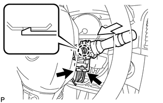
(b) Connect the 2 connectors.
2. INSTALL UPPER STEERING COLUMN COVER
|
(a) Engage the 3 claws and 4 clips to install the upper steering column cover to the lower instrument cover. |
|
.png)
3. INSTALL LOWER STEERING COLUMN COVER
|
(a) Engage the 3 claws to install the lower steering column cover to the upper steering column cover. |
|
.png)
|
(b) Turn the steering wheel assembly to the left and install the screw shown in the illustration. |
|
.png)
|
(c) Turn the steering wheel assembly to the right and install the screw shown in the illustration. |
|
.png)
4. INSTALL LOWER NO. 1 INSTRUMENT PANEL FINISH PANEL
.gif)
5. INSTALL COWL SIDE TRIM SUB-ASSEMBLY LH
6. INSTALL FRONT DOOR SCUFF PLATE LH
 Inspection
INSPECTION
PROCEDURE
1. INSPECT WINDSHIELD WIPER SWITCH ASSEMBLY
(a) Measure the resistance according to the value(s) in the table below.
Standard Resistance:
Front Wiper Switch
...
 Door Lock
...
Other materials about Toyota Venza:
Transponder Chip Malfunction (B2793)
DESCRIPTION
This DTC is stored when a malfunction is found in the key during key code registration
or a key code is not registered normally. Replace the key if the key code registration
is not performed normally and this DTC is detected.
DTC N ...
Performance Decline of Brake Function (C1441)
DESCRIPTION
The skid control ECU judges brake failure conditions have occurred based on the
signal from the brake pedal load sensing switch and master cylinder pressure sensor.
NOTICE:
Do not intentionally stop the engine when driving. Even when no malfun ...
Opening the fuel tank cap
Perform the following steps to open the fuel tank cap.
- Before refueling the vehicle
• Vehicles with smart key system
Turn the “ENGINE START STOP” switch off and ensure that all the doors and windows
are closed.
• Vehicles without smart ke ...

0.1529