Toyota Venza: Switch Failure (B2342)
DESCRIPTION
This DTC is output when the sliding roof ECU (sliding roof drive gear sub-assembly) detects that the sliding roof switch is stuck for 30 seconds or more.
|
DTC Code |
DTC Detection Condition |
Trouble Area |
|---|---|---|
|
B2342 |
Sliding roof ECU (sliding roof drive gear sub-assembly) detects sliding roof switch is stuck for 30 seconds or more. |
|
WIRING DIAGRAM
Refer to DTC B2341 (See page .gif) ).
).
CAUTION / NOTICE / HINT
NOTICE:
- Inspect the fuses for circuits related to this system before performing the following inspection procedure.
- When the sliding roof ECU (sliding roof drive gear sub-assembly) is
replaced or removed and reinstalled, it requires initialization (See page
).
PROCEDURE
|
1. |
READ VALUE USING TECHSTREAM (SLIDING ROOF SWITCH) |
(a) Connect the Techstream to the DLC3.
(b) Turn the ignition switch to ON.
(c) Turn the Techstream on.
(d) Enter the following menus: Body Electrical / Slide Roof / Data List.
(e) Read the Data List according to the display on the Techstream.
Slide Roof (Sliding Roof ECU (Sliding Roof Drive Gear Sub-assembly))|
Tester Display |
Measurement Item/Range |
Normal Condition |
Diagnostic Note |
|---|---|---|---|
|
Open Switch Failure (Current) |
Open switch failure signal (Current)/Fail or Not Fail |
Fail: Sliding roof open signal failure (Current) Not Fail: Sliding roof open signal not fail (Current) |
- |
|
Close Switch Failure (Current) |
Close switch failure signal (Current)/Fail or Not Fail |
Fail: Sliding roof close signal failure (Current) Not Fail: Sliding roof close signal not fail (Current) |
- |
|
Up Switch Failure (Current) |
Up switch failure signal (Current)/Fail or Not Fail |
Fail: Sliding roof tilt up signal failure (Current) Not Fail: Sliding roof tilt up signal not fail (Current) |
- |
|
Down Switch Failure (Current) |
Down switch failure signal (Current)/Fail or Not Fail |
Fail: Sliding roof tilt down signal failure (Current) Not Fail: Sliding roof tilt down signal not fail (Current) |
- |
OK:
"Not Fail" appears on the Techstream screen.
| OK | .gif) |
REPLACE SLIDING ROOF ECU (SLIDING ROOF DRIVE GEAR SUB-ASSEMBLY) |
|
.gif)
|
2. |
CHECK HARNESS AND CONNECTOR (SLIDING ROOF ECU - BODY GROUND) |
|
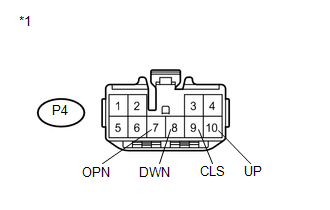
(a) Disconnect the P4 ECU connector. |
|
(b) Disconnect the P6 switch connector.
(c) Measure the resistance according to the value(s) in the table below.
Standard Resistance:
|
Tester Connection |
Condition |
Specified Condition |
|---|---|---|
|
P4-7 (OPN) - Body ground |
Always |
10 kΩ or higher |
|
P4-8 (DWN) - Body ground |
Always |
10 kΩ or higher |
|
P4-9 (CLS) - Body ground |
Always |
10 kΩ or higher |
|
P4-10 (UP) - Body ground |
Always |
10 kΩ or higher |
|
*1 |
Front view of wire harness connector (to Sliding Roof ECU (Sliding Roof Drive Gear Sub-assembly)) |
| NG | |
REPAIR OR REPLACE HARNESS OR CONNECTOR |
|
|
3. |
CHECK HARNESS AND CONNECTOR (SLIDING ROOF SWITCH (ROOF CONSOLE BOX ASSEMBLY)) |
|
(a) Reconnect the P6 switch connector. |
|
(b) Measure the resistance according to the value(s) in the table below.
Standard Resistance:
|
Tester Connection |
Condition |
Specified Condition |
|---|---|---|
|
P4-7 (OPN) - Body ground |
SLIDE OPEN switch off |
10 kΩ or higher |
|
P4-8 (DWN) - Body ground |
TILT DOWN switch off |
10 kΩ or higher |
|
P4-9 (CLS) - Body ground |
SLIDE CLOSE switch off |
10 kΩ or higher |
|
P4-10 (UP) - Body ground |
TILT UP switch off |
10 kΩ or higher |
|
*1 |
Front view of wire harness connector (to Sliding Roof ECU (Sliding Roof Drive Gear Sub-assembly)) |
| OK | |
REPLACE SLIDING ROOF ECU (SLIDING ROOF DRIVE GEAR SUB-ASSEMBLY) |
| NG | |
REPLACE SLIDING ROOF SWITCH (ROOF CONSOLE BOX ASSEMBLY) |
 Diagnostic Trouble Code Chart
DIAGNOSTIC TROUBLE CODE CHART
Sliding Roof (Sliding Roof ECU (Sliding Roof Drive Gear Sub-assembly))
DTC Code
Detection Item
Trouble Area
See page
...
 Sensor (Motor) Failure (B2341,B2344)
DESCRIPTION
When the sliding roof ECU (sliding roof drive gear sub-assembly) detects a motor
malfunction and the sliding roof operation is stopped, DTC B2341 is output.
When the sliding roof ECU ( ...
Other materials about Toyota Venza:
Terminals Of Ecu
TERMINALS OF ECU
1. CENTER AIRBAG SENSOR ASSEMBLY
Terminal No.
Terminal Symbol
Destination
L31-1
SFL+
Front seat side airbag assembly LH (Side squib LH)
L31-2
...
Disassembly
DISASSEMBLY
PROCEDURE
1. REMOVE BRAKE PEDAL RETURN SPRING
(a) Remove the brake pedal return spring from the brake pedal support
assembly.
2. REMOVE BRAKE PEDAL PAD
(a) Remove the brake pedal pa ...
Automatic High Beam System (B124B)
DESCRIPTION
The DTC is stored when the main body ECU (driver side junction block assembly)
detects malfunctions in the automatic high beam system.
DTC No.
DTC Detection Condition
Trouble Area
B124B
...

0.1166