Toyota Venza: Light Control Switch Circuit
DESCRIPTION
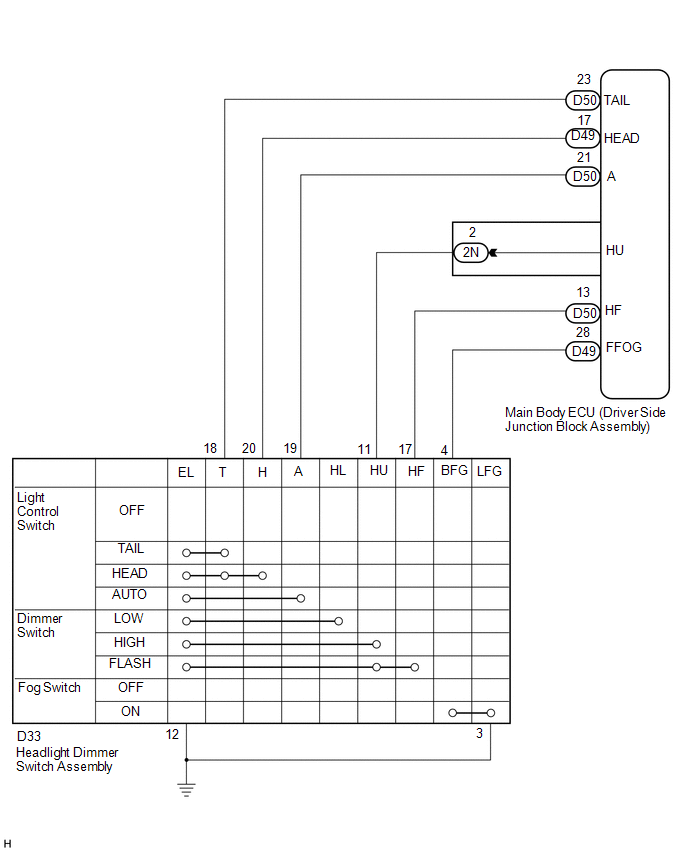
The main body ECU (driver side junction block assembly) receives the following switch information:
- Light control switch position off, tail, head or AUTO
- Dimmer switch position high, low or high flash (pass)
- Fog light switch position on or off
WIRING DIAGRAM
PROCEDURE
|
1. |
READ VALUE USING TECHSTREAM |
(a) Connect the Techstream to the DLC3.
(b) Turn the ignition switch to ON.
(c) Turn the Techstream on.
(d) Enter the following menus: Body Electrical / Main Body / Data List.
(e) Read Data List according to the display on the Techstream.
Main Body|
Tester Display |
Measurement Item/Range |
Normal Condition |
Diagnostic Note |
|---|---|---|---|
|
Dimmer Hi SW |
Dimmer switch high position signal/ON or OFF |
ON: Dimmer switch in high or high flash (pass) position OFF: Dimmer switch in low position |
- |
|
Passing Light SW |
Dimmer switch high flash (pass) position signal/ON or OFF |
ON: Dimmer switch in high flash (pass) position OFF: Dimmer switch not in high flash (pass) position |
- |
|
Front Fog Light SW |
Front fog light switch signal/ON or OFF |
ON: Front fog light switch on OFF: Front fog light switch off |
- |
|
Auto Light SW |
Light control switch AUTO position signal/ON or OFF |
ON: Light control switch in AUTO position OFF: Light control switch not in AUTO position |
- |
|
Head Light SW (Head) |
Light control switch head position signal/ON or OFF |
ON: Light control switch in head position OFF: Light control switch not in head position |
- |
|
Head Light SW (Tail) |
Light control switch tail position signal/ON or OFF |
ON: Light control switch in tail or head position OFF: Light control switch in neither tail nor head position |
- |
OK:
Normal conditions listed above are displayed.
| OK | .gif) |
PROCEED TO NEXT SUSPECTED AREA SHOWN IN PROBLEM SYMPTOMS TABLE |
|
.gif)
|
2. |
INSPECT HEADLIGHT DIMMER SWITCH ASSEMBLY |
HINT:
Inspect the items that did not change as a result of monitoring the Data List.
|
(a) Remove the headlight dimmer switch assembly (See page
|
|
.gif) ).
).
(b) Measure the resistance according to the value(s) in the table below.
Standard Resistance:
Light Control Switch|
Tester Connection |
Condition |
Specified Condition |
|---|---|---|
|
12 (EL) - 18 (T) |
OFF |
10 kΩ or higher |
|
18 (T) - 19 (A) |
OFF |
10 kΩ or higher |
|
19 (A) - 20 (H) |
OFF |
10 kΩ or higher |
|
12 (EL) - 18 (T) |
TAIL |
Below 1 Ω |
|
12 (EL) - 18 (T) |
HEAD |
Below 1 Ω |
|
18 (T) - 20 (H) |
HEAD |
Below 1 Ω |
|
12 (EL) - 19 (A) |
AUTO |
Below 1 Ω |
|
Tester Connection |
Condition |
Specified Condition |
|---|---|---|
|
11 (HU) - 12 (EL) |
LOW |
10 kΩ or higher |
|
11 (HU) - 12 (EL) |
HIGH |
Below 1 Ω |
|
12 (EL) - 17 (HF) |
HIGH FLASH |
Below 1 Ω |
|
Tester Connection |
Condition |
Specified Condition |
|---|---|---|
|
3 (LFG) - 4 (BFG) |
OFF |
10 kΩ or higher |
|
3 (LFG) - 4 (BFG) |
ON |
Below 1 Ω |
OK:
Headlight dimmer switch assembly is normal.
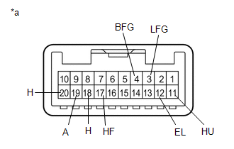
Text in Illustration|
*a |
Component without harness connected: (Headlight Dimmer Switch Assembly) |
| NG | |
REPLACE HEADLIGHT DIMMER SWITCH ASSEMBLY |
|
|
3. |
CHECK HARNESS AND CONNECTOR (MAIN BODY ECU (DRIVER SIDE JUNCTION BLOCK ASSEMBLY - HEADLIGHT DIMMER SWITCH ASSEMBLY |
(a) Disconnect the D33 headlight dimmer switch assembly connector.
(b) Disconnect the D49, D50 and 2N main body ECU (driver side junction block assembly) connectors.
(c) Measure the resistance according to the value(s) in the table below.
Standard Resistance:
|
Tester Connection |
Condition |
Specified Condition |
|---|---|---|
|
D33-4 (BFG) - D49-28 (FFOG) |
Always |
Below 1 Ω |
|
D33-11 (HU) - 2N-2 (HU) |
Always |
Below 1 Ω |
|
D33-17 (HF) - D50-13 (HF) |
Always |
Below 1 Ω |
|
D33-18 (T) - D50-23 (TAIL) |
Always |
Below 1 Ω |
|
D33-19 (A) - D50-21 (A) |
Always |
Below 1 Ω |
|
D33-20 (H) - D49-17 (HEAD) |
Always |
Below 1 Ω |
|
D33-3 (LFG) - Body ground |
Always |
Below 1 Ω |
|
D33-4 (BFG) - Body ground |
Always |
10 kΩ or higher |
|
D33-11 (HU) - Body ground |
Always |
10 kΩ or higher |
|
D33-17 (HF) - Body ground |
Always |
10 kΩ or higher |
|
D33-18 (T) - Body ground |
Always |
10 kΩ or higher |
|
D33-19 (A) - Body ground |
Always |
10 kΩ or higher |
|
D33-20 (H) - Body ground |
Always |
10 kΩ or higher |
|
D33-12 (EL) - Body ground |
Always |
Below 1 Ω |
|
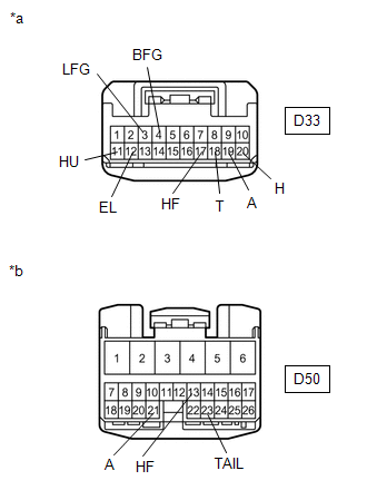
*a |
Front view of wire harness connector (to Headlight Dimmer Switch Assembly) |
|
*b |
Front view of wire harness connector (to Main Body ECU (Driver Side Junction Block Assembly)) |
|
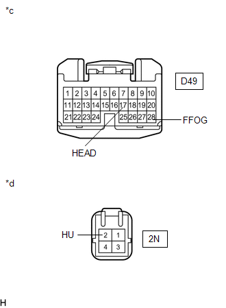
*c |
Front view of wire harness connector (to Main Body ECU (Driver Side Junction Block Assembly)) |
|
*d |
Front view of wire harness connector (to Main Body ECU (Driver Side Junction Block Assembly)) |
| OK | |
REPLACE MAIN BODY ECU (DRIVER SIDE JUNCTION BLOCK ASSEMBLY) |
| NG | |
REPAIR OR REPLACE HARNESS OR CONNECTOR |
 Headlight Signal Circuit
DESCRIPTION
The headlight leveling ECU assembly detects the low beam headlights status.
WIRING DIAGRAM
CAUTION / NOTICE / HINT
NOTICE:
First check that the low beam headlights operate normally. ...
 Door Mirror Foot Light Circuit
DESCRIPTION
The main body ECU (driver side junction block assembly) controls the door mirror
foot lights.
WIRING DIAGRAM
1. w/o Seat Position Memory:
2. w/ Seat Position Memory:
PROCEDURE
...
Other materials about Toyota Venza:
Inspection
INSPECTION
PROCEDURE
1. INSPECT TIE ROD ASSEMBLY LH
(a) Secure the tie rod assembly LH in a vise.
(b) Install the nut to the stud bolt.
(c) Flip the ball joint back and forth 5 times.
(d) Set a to ...
Seat Memory Switch
Components
COMPONENTS
ILLUSTRATION
Removal
REMOVAL
PROCEDURE
1. REMOVE FRONT DOOR INSIDE HANDLE BEZEL PLUG LH
2. REMOVE POWER WINDOW REGULATOR MASTER SWITCH ASSEMBLY WITH FRONT DOOR ARMREST
BASE PANEL
3. REMOVE COURTESY LIGHT ASSEMBLY
...
Reassembly
REASSEMBLY
PROCEDURE
1. INSTALL STIFFENING CRANKCASE RING PIN
NOTICE:
It is not necessary to remove the ring pin unless it is being replaced.
(a) Using a plastic-faced hammer, tap in 2 new ring pins until they stop.
Text in Illustration
...

0.1288