Toyota Venza: Sensor (Motor) Failure (B2341,B2344)
DESCRIPTION
When the sliding roof ECU (sliding roof drive gear sub-assembly) detects a motor malfunction and the sliding roof operation is stopped, DTC B2341 is output.
When the sliding roof ECU (sliding roof drive gear sub-assembly) detects a gear malfunction and the sliding roof operation is stopped, DTC B2344 is output.
|
DTC Code |
DTC Detection Condition |
Trouble Area |
|---|---|---|
|
B2341 |
Sensor (motor) failure (When the ECU enters fail-safe mode due to a problem with the motor) |
|
|
B2344 |
Position failure (When the ECU enters fail-safe mode due to a problem with the gear position) |
|
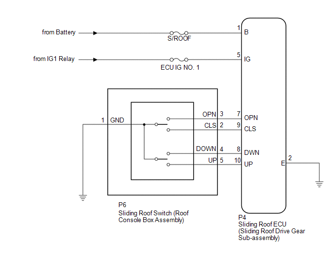
WIRING DIAGRAM
CAUTION / NOTICE / HINT
NOTICE:
- Inspect the fuses for circuits related to this system before performing the following inspection procedure.
- When the sliding roof ECU (sliding roof drive gear sub-assembly) is
replaced or removed and reinstalled, it requires initialization (See page
.gif) ).
).
PROCEDURE
|
1. |
CHECK SLIDING ROOF OPERATION |
(a) Check the sliding roof auto operation (See page
).
OK:
Auto operation operates normally.
| NG | .gif) |
GO TO STEP 3 |
|
.gif)
|
2. |
CHECK DTC OUTPUT |
(a) Clear the DTC (See page ).
(b) Recheck for DTCs.
OK:
DTC B2341 or B2344 is not output.
| OK | |
USE SIMULATION METHOD TO CHECK |
| NG | |
REPLACE SLIDING ROOF ECU (SLIDING ROOF DRIVE GEAR SUB-ASSEMBLY) |
|
3. |
INITIALIZE SLIDING ROOF ECU (SLIDING ROOF DRIVE GEAR SUB-ASSEMBLY) |
(a) Check that the sliding roof ECU (sliding roof drive gear sub-assembly) can
be initialized (See page ).
OK:
Sliding roof ECU (sliding roof drive gear sub-assembly) can be initialized.
| NG | |
GO TO STEP 5 |
|
|
4. |
CHECK DTC OUTPUT |
(a) Clear the DTC (See page ).
(b) Recheck for DTCs.
OK:
DTC B2341 or B2344 is not output.
| OK | |
END |
| NG | |
REPLACE SLIDING ROOF ECU (SLIDING ROOF DRIVE GEAR SUB-ASSEMBLY) |
|
5. |
CHECK HARNESS AND CONNECTOR (SLIDING ROOF ECU - SLIDING ROOF SWITCH) |
|
(a) Disconnect the P6 switch connector. |
|
(b) Disconnect the P4 ECU connector.
(c) Measure the resistance according to the value(s) in the table below.
Standard Resistance:
|
Tester Connection |
Condition |
Specified Condition |
|---|---|---|
|
P4-9 (CLS) - P6-2 (CLS) |
Always |
Below 1 Ω |
|
P4-9 (CLS) - Body ground |
Always |
10 kΩ or higher |
|
P4-7 (OPN) - P6-3 (OPN) |
Always |
Below 1 Ω |
|
P4-7 (OPN) - Body ground |
Always |
10 kΩ or higher |
|
P4-8 (DWN) - P6-4 (DOWN) |
Always |
Below 1 Ω |
|
P4-8 (DWN) - Body ground |
Always |
10 kΩ or higher |
|
P4-10 (UP) - P6-5 (UP) |
Always |
Below 1 Ω |
|
P4-10 (UP) - Body ground |
Always |
10 kΩ or higher |
|
P6-1 (GND) - Body ground |
Always |
Below 1 Ω |
|
P4-2 (E) - Body ground |
Always |
Below 1 Ω |
|
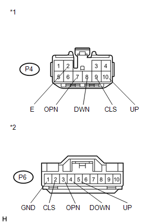
*1 |
Front view of wire harness connector (to Sliding Roof ECU (Sliding Roof Drive Gear Sub-assembly)) |
|
*2 |
Front view of wire harness connector (to Sliding Roof Switch (Roof Console Box Assembly)) |
| NG | |
REPAIR OR REPLACE HARNESS OR CONNECTOR |
|
|
6. |
INSPECT SLIDING ROOF SWITCH (ROOF CONSOLE BOX ASSEMBLY) |
|
(a) Remove the sliding roof switch (roof console box assembly) (See page
|
|
.png)
(b) Measure the resistance according to the value(s) in the table below.
Standard Resistance:
|
Tester Connection |
Condition |
Specified Condition |
|---|---|---|
|
P6-4 (DOWN) - P6-1 (GND) |
TILT DOWN switch is pressed |
Below 1 Ω |
|
P6-4 (DOWN) - P6-1 (GND) |
TILT DOWN switch is not pressed |
10 kΩ or higher |
|
P6-5 (UP) - P6-1 (GND) |
TILT UP switch is pressed |
Below 1 Ω |
|
P6-5 (UP) - P6-1 (GND) |
TILT UP switch is not pressed |
10 kΩ or higher |
|
P6-2 (CLS) - P6-1 (GND) |
SLIDE CLOSE switch is pressed |
Below 1 Ω |
|
P6-2 (CLS) - P6-1 (GND) |
SLIDE CLOSE switch is not pressed |
10 kΩ or higher |
|
P6-3 (OPN) - P6-1 (GND) |
SLIDE OPEN switch is pressed |
Below 1 Ω |
|
P6-3 (OPN) - P6-1 (GND) |
SLIDE OPEN switch is not pressed |
10 kΩ or higher |
|
*1 |
Component without harness connected (Sliding Roof Switch (Roof Console Box Assembly)) |
| OK | |
REPLACE SLIDING ROOF ECU (SLIDING ROOF DRIVE GEAR SUB-ASSEMBLY) |
| NG | |
REPLACE SLIDING ROOF SWITCH (ROOF CONSOLE BOX ASSEMBLY) |
 Switch Failure (B2342)
DESCRIPTION
This DTC is output when the sliding roof ECU (sliding roof drive gear sub-assembly)
detects that the sliding roof switch is stuck for 30 seconds or more.
DTC Code
...
 Sliding Roof does not Move by Operating Sliding Roof Control Switch
DESCRIPTION
The sliding roof ECU (sliding roof drive gear sub-assembly) receives switch slide
and tilt signals and drives its built-in motor.
WIRING DIAGRAM
CAUTION / NOTICE / HINT
NOTICE:
...
Other materials about Toyota Venza:
Precaution
PRECAUTION
1. PRECAUTION FOR DISCONNECTING CABLE FROM NEGATIVE BATTERY TERMINAL
NOTICE:
After the ignition switch is turned off, the radio and display receiver
assembly records various types of memory and settings. As a result, after
turning ...
Intake Manifold Runner Control Circuit Low (Bank 1) (P2009,P2010)
DESCRIPTION
The ECM activates the DC motor for the tumble control valve, which opens and
closes the tumble control valve. The ECM activates the DC motor based on engine
speed, coolant temperature, intake air temperature and other conditions.
D ...
Precaution
PRECAUTION
1. PRECAUTION FOR DISCONNECTING THE BATTERY CABLE
NOTICE:
When disconnecting the cable from the negative (-) battery terminal, initialize
the following systems after the cable is reconnected:
System
See Procedure
...

0.1365