Toyota Venza: Stereo Jack Adapter Assembly
Components
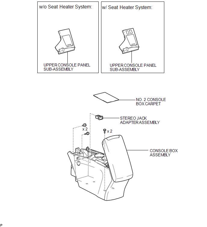
COMPONENTS
ILLUSTRATION
Removal
REMOVAL
PROCEDURE
1. REMOVE UPPER CONSOLE PANEL SUB-ASSEMBLY (w/o Seat Heater System)
.gif)
2. REMOVE UPPER CONSOLE PANEL SUB-ASSEMBLY (w/ Seat Heater System)
3. REMOVE NO. 2 CONSOLE BOX CARPET
4. REMOVE CONSOLE BOX ASSEMBLY
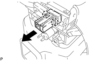
5. REMOVE STEREO JACK ADAPTER ASSEMBLY
|
(a) Disengage the 2 claws and remove the stereo jack adapter assembly as shown in the illustration. |
|
Installation
INSTALLATION
PROCEDURE
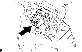
1. INSTALL STEREO JACK ADAPTER ASSEMBLY
|
(a) Engage the 2 claws to install the stereo jack adapter assembly as shown in the illustration. |
|
2. INSTALL CONSOLE BOX ASSEMBLY
.gif)
3. INSTALL NO. 2 CONSOLE BOX CARPET
4. INSTALL UPPER CONSOLE PANEL SUB-ASSEMBLY (w/o Seat Heater System)
5. INSTALL UPPER CONSOLE PANEL SUB-ASSEMBLY (w/ Seat Heater System)
 Stereo Component Amplifier
Components
COMPONENTS
ILLUSTRATION
Removal
REMOVAL
PROCEDURE
1. REMOVE FRONT SEAT ASSEMBLY RH (for Manual Seat)
HINT:
Use the same procedure for the RH side and the LH side (See page
) ...
 Window Glass Antenna Wire
On-vehicle Inspection
ON-VEHICLE INSPECTION
PROCEDURE
1. INSPECT WINDOW GLASS ANTENNA WIRE
(a) Check for continuity of the antenna.
HINT:
Check for continuity at the center of e ...
Other materials about Toyota Venza:
Meter Illumination is Always Dark
DESCRIPTION
In this circuit, the meter CPU receives auto dimmer signals from the main body
ECU (driver side junction block assembly) using the CAN communication system (CAN
No. 1 Bus). When the meter CPU receives an auto dimmer signal, it dims the meter
...
Washer Nozzle(for Front Side)
Components
COMPONENTS
ILLUSTRATION
On-vehicle Inspection
ON-VEHICLE INSPECTION
PROCEDURE
1. INSPECT FRONT WASHER NOZZLE SUB-ASSEMBLY
(a) With the engine running, check that the center stream of washer fluid sprays
on the windshield within the ar ...
Reassembly
REASSEMBLY
PROCEDURE
1. CONNECT WASHER HOSE ASSEMBLY
(a) Engage the 5 clips and connect the washer hose assembly.
2. INSTALL FRONT WASHER NOZZLE SUB-ASSEMBLY
3. INSPECT FRONT WASHER NOZZLE SUB-A ...

0.1645