Toyota Venza: Stereo Component Amplifier
Components
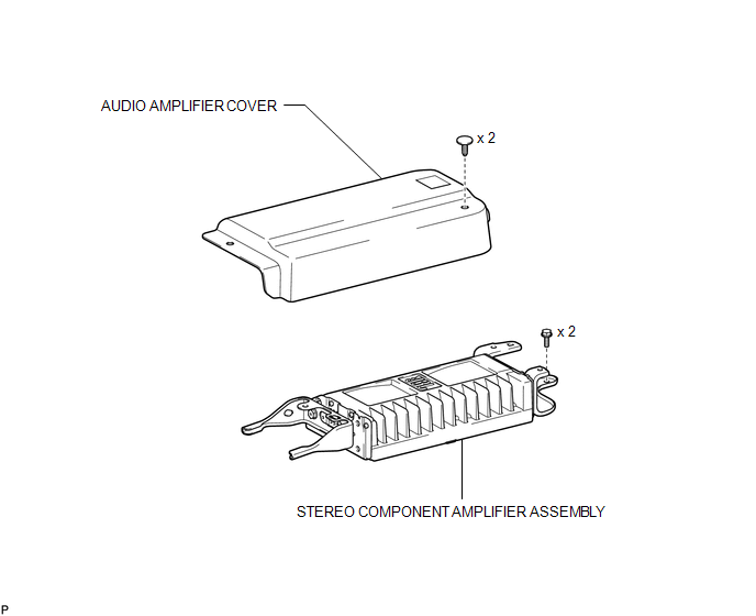
COMPONENTS
ILLUSTRATION
Removal
REMOVAL
PROCEDURE
1. REMOVE FRONT SEAT ASSEMBLY RH (for Manual Seat)
HINT:
Use the same procedure for the RH side and the LH side (See page
.gif) ).
).
2. REMOVE FRONT SEAT ASSEMBLY RH (for Power Seat)
HINT:
Use the same procedure for the RH side and the LH side (See page
).
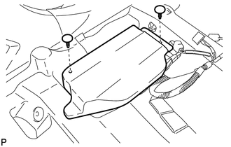
3. REMOVE AUDIO AMPLIFIER COVER
|
(a) Using a clip remover, remove the 2 clips and audio amplifier cover. |
|
4. REMOVE STEREO COMPONENT AMPLIFIER ASSEMBLY
|
(a) Disconnect the 4 connectors. |
|
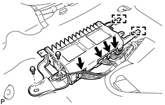
(b) Remove the 2 bolts.
(c) Disengage the 2 guides and remove the stereo component amplifier assembly.
Installation
INSTALLATION
PROCEDURE
1. INSTALL STEREO COMPONENT AMPLIFIER ASSEMBLY
|
(a) Engage the 2 guides. |
|
.png)
(b) Install the stereo component amplifier assembly with the 2 bolts.
(c) Connect the 4 connectors.
2. INSTALL AUDIO AMPLIFIER COVER
|
(a) Install the audio amplifier cover with the 2 clips. |
|
.png)
3. INSTALL FRONT SEAT ASSEMBLY RH (for Manual Seat)
HINT:
Use the same procedure for the RH side and the LH side (See page
.gif) ).
).
4. INSTALL FRONT SEAT ASSEMBLY RH (for Power Seat)
HINT:
Use the same procedure for the RH side and the LH side (See page
).
 Installation
INSTALLATION
PROCEDURE
1. INSTALL STEREO COMPONENT TUNER ASSEMBLY
2. INSTALL NAVIGATION WIRE
(a) Connect the 3 connectors to install the navigation wire.
3. INSTALL STEREO COMPONENT TUNER ASSEMBL ...
 Stereo Jack Adapter Assembly
Components
COMPONENTS
ILLUSTRATION
Removal
REMOVAL
PROCEDURE
1. REMOVE UPPER CONSOLE PANEL SUB-ASSEMBLY (w/o Seat Heater System)
2. REMOVE UPPER CONSOLE PANEL SUB-ASSEMBLY (w/ Seat Hea ...
Other materials about Toyota Venza:
Inspection
INSPECTION
PROCEDURE
1. INSPECT REAR NO. 3 SPEAKER ASSEMBLY (for 13 Speakers)
(a) With the speaker installed, check that there is no looseness or other abnormalities.
(b) Check that there is no foreign matter in the speaker, no tears on the speaker
cone ...
Security Horn Assembly
Removal
REMOVAL
PROCEDURE
1. REMOVE SECURITY HORN ASSEMBLY
(a) Remove the bolt and disconnect the security horn assembly.
(b) Disconnect the connector and remove the security horn asse ...
Inspection
INSPECTION
PROCEDURE
1. INSPECT CYLINDER HEAD SUB-ASSEMBLY
(a) Using a precision straightedge and feeler gauge, measure the warpage of the
contact surfaces where the cylinder head contacts the cylinder block and manifold.
Maximum Warpage:
...

0.1621