Toyota Venza: A/F Sensor Slow Response - Rich to Lean Bank 1 Sensor 1 (P014C,P014D,P015A,P015B)
DESCRIPTION
HINT:
Refer to DTC P2195 (See page .gif) ).
).
|
DTC No. |
DTC Detection Condition |
Trouble Area |
|---|---|---|
|
P014C |
The "Rich to Lean response rate deterioration level*" value is standard or less (2 trip detection logic). |
|
|
P014D |
The "Lean to Rich response rate deterioration level*" value is standard or more (2 trip detection logic). |
|
|
P015A |
The "Rich to Lean delay level*" value is standard or more (2 trip detection logic). |
|
|
P015B |
The "Lean to Rich delay level*" value is standard or more (2 trip detection logic). |
*: Calculated by ECM based on the air fuel ratio sensor output.
MONITOR DESCRIPTION
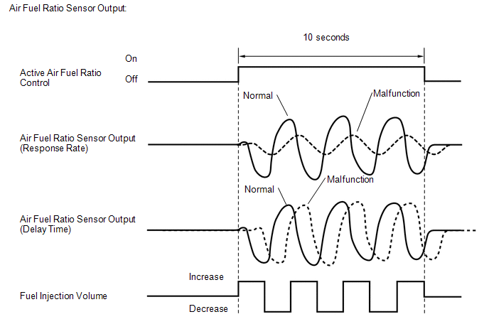
After the engine has been warmed up, the ECM carries out air fuel ratio feedback control, and maintains the air fuel ratio at the theoretical level. In addition, after all the preconditions have been met, active air fuel ratio control is carried out for approximately 10 seconds and during active air fuel ratio control, the ECM measures the response of the air fuel ratio sensor by increasing or decreasing a specific injection quantity based on the theoretical air fuel ratio learned during normal air fuel control. The ECM determines whether there is an air fuel ratio sensor malfunction at the mid-point of active air fuel ratio control.
If the air fuel ratio sensor's response ability is reduced, DTC P014C and P014D are output.
If the air fuel ratio sensor output timing is delayed, DTC P015A and P015B are output.
MONITOR STRATEGY
|
Related DTCs |
P014C: Air fuel ratio sensor (sensor 1) response rate (rich to lean response rate) P014D: Air fuel ratio sensor (sensor 1) response rate (lean to rich response rate) P015A: Air fuel ratio sensor (sensor 1) response rate (rich to lean delay) P015B: Air fuel ratio sensor (sensor 1) response rate (lean to rich delay) |
|
Required Sensors/Components (Main) |
Air fuel ratio sensor |
|
Required Sensors/Components (Related) |
Vehicle speed sensor Crankshaft position sensor |
|
Frequency of Operation |
Once per driving cycle |
|
Duration |
10 to 15 seconds |
|
MIL Operation |
2 driving cycles |
|
Sequence of Operation |
None |
TYPICAL ENABLING CONDITIONS
|
Monitor runs whenever the following DTCs are not stored |
None |
|
Active air fuel ratio control |
Performing |
|
Active air fuel ratio control is performed when the following conditions are met |
- |
|
Battery voltage |
11 V or higher |
|
Engine coolant temperature |
75°C (167°F) or higher |
|
Idle |
Off |
|
Engine speed |
1200 rpm or higher, and less than 2500 rpm |
|
Air fuel ratio sensor status |
Activated |
|
Fuel-cut |
Off |
|
Engine load |
10% or higher, and less than 70% |
|
Shift position |
2nd or more |
|
Catalyst monitor |
Not yet |
|
Mass air flow |
4 gm/sec or more, and less than 16 gm/sec |
TYPICAL MALFUNCTION THRESHOLDS
P014C: Air Fuel Ratio Sensor (Bank 1) Response Rate (Rich to Lean Response Rate)|
Rich to Lean Response rate deterioration level |
0.032 V or less |
|
Lean to Rich Response rate deterioration level |
-0.0401 V or higher |
|
Rich to Lean delay level |
376.832 ms or more |
|
Lean to Rich delay level |
376.832 ms or more |
MONITOR RESULT
Refer to Checking Monitor Status (See page
).
CONFIRMATION DRIVING PATTERN
HINT:
Performing this confirmation pattern will activate the air fuel ratio sensor response monitor.
- Connect the Techstream to the DLC3.
- Turn the ignition switch to ON.
- Turn the Techstream on.
- Clear the DTCs (even if no DTCs are stored, perform the clear DTC procedure).
- Turn the ignition switch off and wait for at least 30 seconds.
- Turn the ignition switch to ON and turn the Techstream on.
- Enter the following menus: Powertrain / Engine / Monitor / Current Monitor.
- Check that O2 Sensor / Current is Incomplete.
HINT:
The test values for the test items RL RES RATE B1S1, LR RES RATE B1S1, RL DELAY B1S1 and LR DELAY B1S1 do not exist in the Detail of O2 Sensor monitor at this time (the initial value of "0.000" is indicated in each test item).
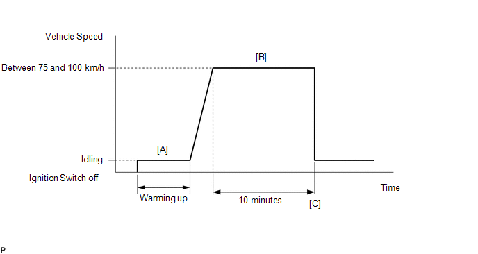
- Start the engine and warm it up (until the engine coolant temperature is 75°C (167°F) or higher) [A].
- Drive the vehicle at a constant speed between 75 and 100 km/h (47 and
62 mph) for 10 minutes [B].
CAUTION:
When performing the confirmation driving pattern, obey all speed limits and traffic laws.
- Check that O2 Sensor / Current becomes Complete.
HINT:
Check the test values on the Techstream by entering the following menus: Powertrain / Engine / Monitor / Current Monitor / O2 Sensor / Details / RL RES RATE B1S1, LR RES RATE B1S1, RL DELAY B1S1 and LR DELAY B1S1.
- If the monitor item O2 Sensor / Current does not become Complete (if
the test values indicated on the Techstream do not change), perform Readiness
Monitor Drive Pattern for the air fuel ratio sensor and heated oxygen sensor
(See page ).
- Enter the following menus: Powertrain / Engine / Trouble Codes [C].
- Read the pending DTCs.
HINT:
- If a pending DTC is output, the system is malfunctioning.
- If a pending DTC is not output, perform the following procedure.
- Enter the following menus: Powertrain / Engine / Utility / All Readiness.
- Input the DTC: P014C, P014D, P015A or P015B.
- Check the DTC judgment result.
Techstream Display
Description
NORMAL
- DTC judgment completed
- System normal
ABNORMAL
- DTC judgment completed
- System abnormal
INCOMPLETE
- DTC judgment not completed
- Perform driving pattern after confirming DTC enabling conditions
N/A
- Unable to perform DTC judgment
- Number of DTCs which do not fulfill DTC preconditions has reached ECU memory limit
HINT:
- If the judgment result shows NORMAL, the system is normal.
- If the judgment result shows ABNORMAL, the system has a malfunction.
- If the judgment result is INCOMPLETE or N/A, drive the vehicle again under an increased load and then recheck the judgment result.
- If no pending DTC is output, perform a universal trip and check for
permanent DTCs (See page ).
HINT:
- If a permanent DTC is output, the system is malfunctioning.
- If no permanent DTC is output, the system is normal.
WIRING DIAGRAM
Refer to DTC P2195 (See page ).
CAUTION / NOTICE / HINT
NOTICE:
Inspect the fuses for circuits related to this system before performing the following inspection procedure.
HINT:
- A low air fuel ratio sensor voltage could be caused by a rich air fuel mixture. Check for conditions that would cause the engine to run rich.
- A high air fuel ratio sensor voltage could be caused by a lean air fuel mixture. Check for conditions that would cause the engine to run lean.
- Read freeze frame data using the Techstream. The ECM records vehicle and driving condition information as freeze frame data the moment a DTC is stored. When troubleshooting, freeze frame data can be helpful in determining whether the vehicle was running or stopped, whether the engine was warmed up or not, whether the air fuel ratio was lean or rich, as well as other data recorded at the time of a malfunction.
- Sensor 1 refers to the sensor closest to the engine assembly.
- Sensor 2 refers to the sensor farthest away from the engine assembly.
PROCEDURE
|
1. |
CHECK ANY OTHER DTCS OUTPUT (IN ADDITION TO DTC P014C, P014D, P015A OR P015B) |
(a) Connect the Techstream to the DLC3.
(b) Turn the ignition switch to ON.
(c) Turn the Techstream on.
(d) Enter the following menus: Powertrain / Engine / Trouble Codes.
(e) Read the DTCs.
Result|
Result |
Proceed to |
|---|---|
|
DTC P014C, P014D, P015A or P015B is output |
A |
|
DTC P014C, P014D, P015A or P015B and other DTCs are output |
B |
HINT:
If any DTCs other than P014C, P014D, P015A or P015B are output, troubleshoot those DTCs first.
| B | .gif) |
GO TO DTC CHART |
|
.gif)
|
2. |
INSPECT AIR FUEL RATIO SENSOR (HEATER RESISTANCE) |
| NG | |
REPLACE AIR FUEL RATIO SENSOR |
|
|
3. |
CHECK HARNESS AND CONNECTOR (AIR FUEL RATIO SENSOR - ECM) |
| NG | |
REPAIR OR REPLACE HARNESS OR CONNECTOR |
|
|
4. |
INSPECT AIR FUEL RATIO SENSOR |
(a) Check that the proper air fuel ratio sensors are installed to the vehicle.
HINT:
Perform "Inspection After Repair" after replacing the air fuel ratio sensor (See
page ).
| NG | |
REPLACE AIR FUEL RATIO SENSOR |
|
|
5. |
PERFORM CONFIRMATION DRIVING PATTERN |
(a) Drive the vehicle according to the Confirmation Driving Pattern.
|
|
6. |
CHECK WHETHER DTC OUTPUT RECURS (DTC P014C, P014D, P015A OR P015B) |
(a) Connect the Techstream to the DLC3.
(b) Turn the ignition switch to ON.
(c) Turn the Techstream on.
(d) Enter the following menus: Powertrain / Engine / Trouble Codes / Pending.
(e) Read the pending DTCs.
Result|
Result |
Proceed to |
|---|---|
|
DTC P014C, P014D, P015A or P015B are output |
A |
|
DTC is not output |
B |
| B | |
CHECK FOR INTERMITTENT PROBLEMS |
|
|
7. |
REPLACE AIR FUEL RATIO SENSOR |
(a) Replace the air fuel ratio sensor (See page
).
HINT:
Perform "Inspection After Repair" after replacing the air fuel ratio sensor (See
page ).
|
|
8. |
PERFORM CONFIRMATION DRIVING PATTERN |
(a) Drive the vehicle according to the Confirmation Driving Pattern.
|
|
9. |
CHECK WHETHER DTC OUTPUT RECURS (DTC P014C, P014D, P015A OR P015B) |
(a) Connect the Techstream to the DLC3.
(b) Turn the ignition switch to ON.
(c) Turn the Techstream on.
(d) Enter the following menus: Powertrain / Engine / Trouble Codes / Pending.
(e) Read the pending DTCs.
Result|
Result |
Proceed to |
|---|---|
|
DTC is not output |
A |
|
DTC P014C, P014D, P015A or P015B are output |
B |
| A | |
END |
| B | |
CHECK ENGINE TO DETERMINE CAUSE OF EXTREMELY RICH OR LEAN ACTUAL AIR FUEL RATIO |
 Coolant Thermostat (Coolant Temperature Below Thermostat Regulating Temperature)
(P0128)
Coolant Thermostat (Coolant Temperature Below Thermostat Regulating Temperature)
(P0128)
DESCRIPTION
HINT:
This DTC relates to the thermostat.
This DTC is stored when the engine coolant temperature does not reach 75°C (167°F)
despite sufficient engine warm-up time having elapsed.
...
 System Too Lean (Bank 1) (P0171,P0172)
DESCRIPTION
The fuel trim is related to the feedback compensation value, not to the basic
injection duration. The fuel trim consists of both the short-term and long-term
fuel trims.
The short-te ...
Other materials about Toyota Venza:
Variation Error (B2453)
DESCRIPTION
This DTC is stored if the headlight leveling ECU assembly for another destination
is installed on the vehicle.
DTC No.
DTC Detecting Condition
Trouble Area
B2453
The headlight levelin ...
Installation
INSTALLATION
PROCEDURE
1. TEMPORARILY INSTALL REAR NO. 1 SUSPENSION ARM ASSEMBLY LH
(a) Temporarily install the rear No. 1 suspension arm assembly LH to
the rear suspension member with the bolt (B).
Text in Illustration
...
Removal
REMOVAL
CAUTION / NOTICE / HINT
HINT:
Use the same procedure for the RH side and LH side.
The procedure listed below is for the LH side.
PROCEDURE
1. PRECAUTION
CAUTION:
Be sure to read Precaution thoroughly before servicing (See page
...

0.1237