Toyota Venza: Interior Light Circuit
DESCRIPTION
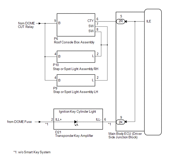
The illuminated entry system controls the roof console box assembly, step or spot light assembly and transponder key amplifier*1.
HINT:
*1: w/o Smart Key System
WIRING DIAGRAM
PROCEDURE
|
1. |
PERFORM ACTIVE TEST USING TECHSTREAM |
(a) Connect the Techstream to the DLC3.
(b) Turn the ignition switch to ON.
(c) Turn the Techstream on.
(d) Enter the following menus: Body Electrical / Main Body / Active Test.
(e) Check that the lights operate.
Main Body|
Tester Display |
Test Part |
Control Range |
Diagnostic Note |
|---|---|---|---|
|
Illuminated Entry System |
Roof console box assembly, step or spot light assembly and transponder key amplifier |
ON/OFF |
Interior light switch is in the DOOR position and all doors are closed. |
OK:
Each light fades in.
| OK | .gif) |
PROCEED TO NEXT SUSPECTED AREA SHOWN IN PROBLEM SYMPTOMS TABLE |
|
.gif)
|
2. |
INSPECT MAIN BODY ECU (DRIVER SIDE JUNCTION BLOCK ASSEMBLY) |
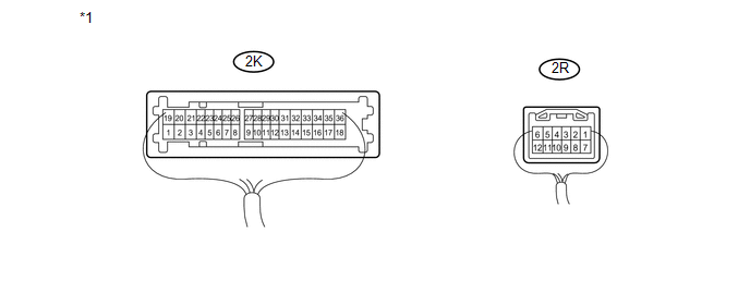
(a) Measure the voltage according to the value(s) in the table below.
 Text in Illustration
|
*1 |
Component with harness connected (Main Body ECU (Driver Side Junction Block Assembly)) |
- |
- |
Standard Voltage:
|
Tester Connection |
Condition |
Specified Condition |
|---|---|---|
|
2K-9 - Body ground |
Ignition key cylinder light off |
11 to 14 V |
|
2R-5 - Body ground |
Interior light switch in DOOR position and Interior lights off |
11 to 14 V |
| OK | |
REPLACE MAIN BODY ECU (DRIVER SIDE JUNCTION BLOCK ASSEMBLY) |
| NG | |
REPAIR OR REPLACE HARNESS OR CONNECTOR |
 Door Courtesy Switch Circuit
DESCRIPTION
The main body ECU (driver side junction block assembly) detects the condition
of the door courtesy light switch.
WIRING DIAGRAM
PROCEDURE
1.
READ VALUE USING ...
 Interior Light Auto Cut Circuit
DESCRIPTION
When battery saving control operates while the interior lights are on, the main
body ECU (driver side junction block assembly) opens the DOME CUT relay to turn
off the lights.
WIRING ...
Other materials about Toyota Venza:
Lost Communication with Rear Gate Module (U0230)
DESCRIPTION
DTC No.
DTC Detection Condition
Trouble Area
U0230
No communication from the power back door ECU (back door motor unit)
or back door closer ECU continues.
Power ...
Disassembly
DISASSEMBLY
PROCEDURE
1. REMOVE GENERATOR REAR END COVER
(a) Remove the 3 nuts and generator rear end cover.
2. REMOVE TERMINAL INSULATOR
(a) Remove the terminal insulator from the gener ...
Headlight Solenoid Circuit
DESCRIPTION
for HID Headlight:
When the main body ECU receives a high beam turn on signal, the main
body ECU activates the bi-function by controlling the BI-XENON relay. The
bi-function increases the upper illumination area of the discharge ...

0.1571