Toyota Venza: Headlight Leveling Ecu
Components
COMPONENTS
ILLUSTRATION
Removal
REMOVAL
PROCEDURE
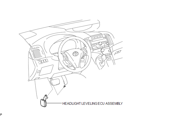
1. REMOVE HEADLIGHT LEVELING ECU ASSEMBLY
|
(a) Disconnect the connector. |
|
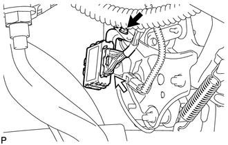
(b) Remove the bolt and headlight leveling ECU assembly.
Installation
INSTALLATION
PROCEDURE
1. INSTALL HEADLIGHT LEVELING ECU ASSEMBLY
|
(a) Install the headlight leveling ECU assembly with the bolt. |
|
.png)
(b) Connect the connector.
2. HEIGHT CONTROL SENSOR SIGNAL INITIALIZATION
(See page .gif) )
)
3. PREPARE VEHICLE FOR HEADLIGHT AIM ADJUSTMENT
4. PREPARE FOR HEADLIGHT AIMING
5. INSPECT HEADLIGHT AIMING
6. ADJUST HEADLIGHT AIMING
 Headlight Dimmer Switch
Components
COMPONENTS
ILLUSTRATION
Removal
REMOVAL
PROCEDURE
1. REMOVE SPIRAL CABLE WITH SENSOR SUB-ASSEMBLY
(See page )
2. REMOVE WINDSHIELD WIPER SWITCH ASSEMBLY
3. REMOVE HEADLIG ...
 Height Control Sensor
Components
COMPONENTS
ILLUSTRATION
ILLUSTRATION
Removal
REMOVAL
PROCEDURE
1. REMOVE REAR HEIGHT CONTROL SENSOR SUB-ASSEMBLY (for 2WD)
(a) Disconnect the connector.
...
Other materials about Toyota Venza:
On-vehicle Inspection
ON-VEHICLE INSPECTION
PROCEDURE
1. CHECK THROTTLE BODY ASSEMBLY
(a) Check the throttle control motor operating sounds.
(1) Turn the ignition switch to ON.
(2) When pressing the accelerator pedal, check the operating sound of the running
motor. Make sure ...
Auxiliary boxes
►Type A (driver’s side instrument panel)
Push down the knob.
►Type B (front console)
Lift the lid.
►Type C (front console)
Lift the lid.
►Type D (front passenger’s side instrument
panel)
- Coin holder (type A) ...
System Description
SYSTEM DESCRIPTION
1. NAVIGATION SYSTEM OUTLINE
(a) Vehicle position tracking methods
It is essential that the navigation system correctly tracks the current vehicle
position and displays it on the map. There are 2 methods to track the current vehicle
p ...

0.1339