Toyota Venza: Speed Sensor(when Not Using The Engine Support Bridge)
Components
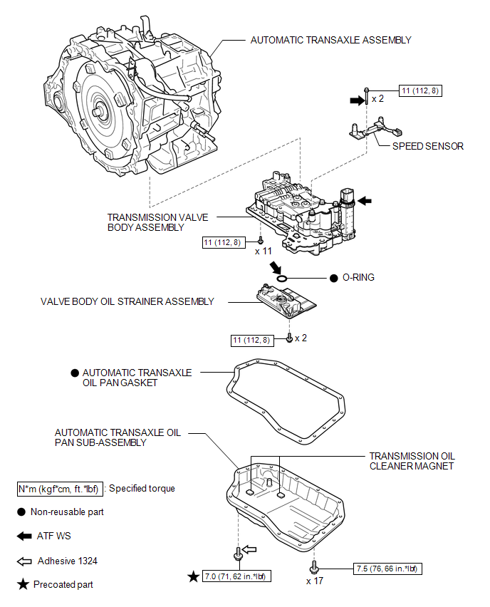
COMPONENTS
ILLUSTRATION
Removal
REMOVAL
PROCEDURE
1. REMOVE AUTOMATIC TRANSAXLE ASSEMBLY
HINT:
See the steps from "Remove Engine Assembly with transaxle" through "Remove Automatic
Transaxle Assembly" (See page .gif) ).
).
2. REMOVE AUTOMATIC TRANSAXLE OIL PAN SUB-ASSEMBLY
3. REMOVE VALVE BODY OIL STRAINER ASSEMBLY
4. REMOVE TRANSMISSION VALVE BODY ASSEMBLY
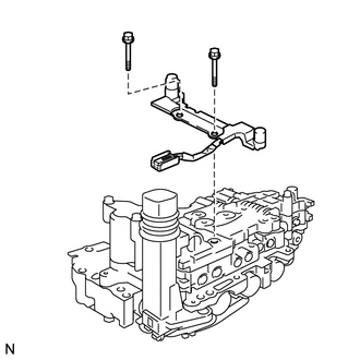
5. REMOVE SPEED SENSOR
(a) Disconnect the speed sensor connector.
|
(b) Remove the 2 bolts and speed sensor from the transmission valve body assembly. |
|
Installation
INSTALLATION
PROCEDURE
1. INSTALL SPEED SENSOR
|
(a) Coat the 2 bolts with ATF. |
|
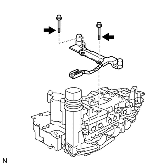
(b) Install the speed sensor to the transmission valve body assembly with the 2 bolts.
Torque:
11 N·m {112 kgf·cm, 8 ft·lbf}
(c) Connect the speed sensor connector.
2. INSTALL TRANSMISSION VALVE BODY ASSEMBLY
.gif)
3. INSTALL VALVE BODY OIL STRAINER ASSEMBLY
4. INSTALL AUTOMATIC TRANSAXLE OIL PAN SUB-ASSEMBLY
5. INSTALL AUTOMATIC TRANSAXLE ASSEMBLY
HINT:
See the steps from "Install Automatic Transaxle Assembly" through "Install Engine
Assembly with Transaxle" (See page ).
 Reassembly
REASSEMBLY
PROCEDURE
1. INSTALL SHIFT LOCK CONTROL COMPUTER SUB-ASSEMBLY
(a) Engage the 3 claws to install the shift lock control computer sub-assembly.
...
 Speed Sensor(when Using The Engine Support Bridge)
Components
COMPONENTS
ILLUSTRATION
Removal
REMOVAL
PROCEDURE
1. REMOVE TRANSMISSION VALVE BODY ASSEMBLY
See page
2. REMOVE SPEED SENSOR
(a) Disconnect the speed sensor connector.
...
Other materials about Toyota Venza:
Removal
REMOVAL
PROCEDURE
1. DISCONNECT CABLE FROM NEGATIVE BATTERY TERMINAL
CAUTION:
Wait at least 90 seconds after disconnecting the cable from the negative (-)
battery terminal to disable the SRS system.
NOTICE:
When disconnecting the cable, some systems ne ...
System Diagram
SYSTEM DIAGRAM
Communication Table
Transmitting ECU (Transmitter)
Receiving ECU (Receiver)
Signal
Line
Main body ECU
(Driver side junction block assembly)
Power Back Door ECU
(P ...
Fuel Sender Open Detected (B1500)
DESCRIPTION
This DTC is output when the combination meter assembly detects a fuel sender
gauge malfunction via the direct line.
DTC No.
DTC Detection Condition
Trouble Area
B1500
When either of t ...

0.1216