Toyota Venza: Slide Sensor Malfunction (B2650)
DESCRIPTION
When the position control ECU and switch assembly does not receive a sensor signal despite forward or backward movement of seat by power seat motor operation, this DTC is output.
|
DTC Code |
DTC Detection Condition |
Trouble Area |
|---|---|---|
|
B2650 |
The forward and backward lock detection position of the sensor is the same. |
|
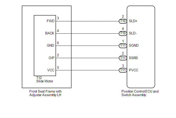
WIRING DIAGRAM
PROCEDURE
|
1. |
CHECK FOR DTC |
(a) Connect the Techstream to the DLC3.
(b) Turn the ignition switch to ON.
(c) Turn the Techstream on.
(d) Enter the following menus: Body Electrical / Driver Seat / Trouble Codes.
(e) Clear the DTC (See page .gif) ).
).
(f) Recheck for DTC B2650.
|
Result |
Proceed to |
|---|---|
|
DTC B2650 is output |
A |
|
DTC B2650 is not output |
B |
| B | .gif) |
USE SIMULATION METHOD TO CHECK |
|
.gif)
|
2. |
PERFORM ACTIVE TEST USING TECHSTREAM |
(a) Enter the following menus: Body Electrical / Driver Seat / Active Test.
(b) Perform the Active Test according to the display on the Techstream.
Driver Seat|
Tester Display |
Test Part |
Control Range |
Diagnostic Note |
|---|---|---|---|
|
Seat Slide Operation |
Seat sliding operation |
OFF/Front/Rear |
- |
OK:
Motor operates normally.
| NG | |
GO TO STEP 5 |
|
|
3. |
CHECK HARNESS AND CONNECTOR (POSITION CONTROL ECU AND SWITCH ASSEMBLY - SLIDE MOTOR) |
(a) Disconnect the T11 the position control ECU and switch assembly connector.
(b) Disconnect the T12 the slide motor (front seat frame with adjuster assembly LH) connector.
(c) Measure the resistance according to the value(s) in the table below.
Standard Resistance:
|
Tester Connection |
Condition |
Specified Condition |
|---|---|---|
|
T11-3 (PVCC) - T12-5 (VCC) |
Always |
Below 1 Ω |
|
T11-2 (SSRS) - T12-2 (O/P) |
Always |
Below 1 Ω |
|
T11-1 (SGND) - T12-6 (GND) |
Always |
Below 1 Ω |
|
T11-3 (PVCC) - Body ground |
Always |
10 kΩ or higher |
|
T11-2 (SSRS) - Body ground |
Always |
10 kΩ or higher |
|
T11-1 (SGND) - Body ground |
Always |
10 kΩ or higher |
| NG | |
REPAIR OR REPLACE HARNESS OR CONNECTOR |
|
|
4. |
CHECK POSITION CONTROL ECU AND SWITCH ASSEMBLY (SLIDE MOTOR CIRCUIT) |
(a) Reconnect the T11 the position control ECU and switch assembly connector.
(b) Measure the voltage according to the value(s) in the table below.
Standard Voltage:
|
Tester Connection |
Condition |
Specified Condition |
|---|---|---|
|
T12-5 (VCC) - T12-6 (GND) |
Slide switch on |
5.5 to 6.5 V |
| OK | |
REPLACE FRONT SEAT FRAME WITH ADJUSTER ASSEMBLY LH |
| NG | |
REPLACE POSITION CONTROL ECU AND SWITCH ASSEMBLY |
|
5. |
INSPECT FRONT SEAT FRAME WITH ADJUSTER ASSEMBLY LH |
(a) Disconnect the T12 the slide motor (front seat frame with adjuster assembly LH) connector.
|
(b) Check if the seat frame moves smoothly when the battery is connected to the slide motor connector terminals. OK:
|
|
| NG | |
REPLACE FRONT SEAT FRAME WITH ADJUSTER ASSEMBLY LH |
|
|
6. |
CHECK HARNESS AND CONNECTOR (POSITION CONTROL ECU AND SWITCH ASSEMBLY - SLIDE MOTOR) |
(a) Disconnect the T10 the position control ECU and switch assembly connector.
(b) Measure the resistance according to the value(s) in the table below.
Standard Resistance:
|
Tester Connection |
Condition |
Specified Condition |
|---|---|---|
|
T10-2 (SLD+) - T12-3 (FWD) |
Always |
Below 1 Ω |
|
T10-4 (SLD-) - T12-4 (BACK) |
Always |
Below 1 Ω |
|
T10-2 (SLD+) - Body ground |
Always |
10 kΩ or higher |
|
T10-4 (SLD-) - Body ground |
Always |
10 kΩ or higher |
| OK | |
REPLACE POSITION CONTROL ECU AND SWITCH ASSEMBLY |
| NG | |
REPAIR OR REPLACE HARNESS OR CONNECTOR |
 Diagnostic Trouble Code Chart
DIAGNOSTIC TROUBLE CODE CHART
If a trouble code is displayed during the DTC check, inspect the trouble areas
listed for that code. For details of the code, refer to the ''See page'' ...
 Short in Sensor with Motor Power Supply Circuit (B2658)
DESCRIPTION
This DTC is stored if sensor voltage does not reach the designated voltage while
the slide motor is operating.
DTC Code
DTC Detection Condition
Trouble ...
Other materials about Toyota Venza:
Power Mirrors do not Return to Memorized Position
SYSTEM DESCRIPTION
If either the M1 or M2 seat memory switch is pressed, the outer mirror control
ECU assembly (driver door) detects the seat memory switch status and sends the switch
signal to the main body ECU (driver side junction block assembly) via C ...
Light Control Switch Circuit
DESCRIPTION
The main body ECU (driver side junction block assembly) receives the following
switch information:
Light control switch position off, tail, head or AUTO
Dimmer switch position high, low or high flash (pass)
Fog light switch posit ...
Inspection
INSPECTION
PROCEDURE
1. INSPECT FRONT SEATBACK HEATER LH
(a) Apply battery voltage and check the seatback heater.
OK:
Measurement Connection
Condition
Specified Condition
...

0.1391