Toyota Venza: Short in Sensor with Motor Power Supply Circuit (B2658)
DESCRIPTION
This DTC is stored if sensor voltage does not reach the designated voltage while the slide motor is operating.
|
DTC Code |
DTC Detection Condition |
Trouble Area |
|---|---|---|
|
B2658 |
Malfunction in supply voltage for the seat slide control position sensor |
|
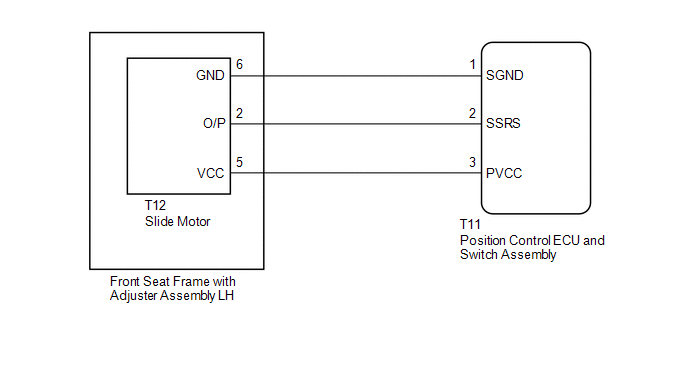
WIRING DIAGRAM
PROCEDURE
|
1. |
CHECK FOR DTC |
(a) Connect the Techstream to the DLC3.
(b) Turn the ignition switch to ON.
(c) Turn the Techstream on.
(d) Enter the following menus: Body Electrical / Driver Seat / Trouble Codes.
(e) Clear the DTC (See page .gif) ).
).
(f) Recheck for DTC B2658.
|
Result |
Proceed to |
|---|---|
|
DTC B2658 is output |
A |
|
DTC B2658 is not output |
B |
| B | .gif) |
USE SIMULATION METHOD TO CHECK |
|
.gif)
|
2. |
CHECK HARNESS AND CONNECTOR (POSITION CONTROL ECU AND SWITCH ASSEMBLY - SLIDE MOTOR) |
(a) Disconnect the T11 the position control ECU and switch assembly connector.
(b) Disconnect the T12 the slide motor (front seat frame with adjuster assembly LH).
(c) Measure the resistance according to the value(s) in the table below.
Standard Resistance:
|
Tester Connection |
Condition |
Specified Condition |
|---|---|---|
|
T11-3 (PVCC) - T12-5 (VCC) |
Always |
Below 1 Ω |
|
T11-2 (SSRS) - T12-2 (O/P) |
Always |
Below 1 Ω |
|
T11-1 (SGND) - T12-6 (GND) |
Always |
Below 1 Ω |
|
T11-3 (PVCC) - Body ground |
Always |
10 kΩ or higher |
|
T11-2 (SSRS) - Body ground |
Always |
10 kΩ or higher |
|
T11-1 (SGND) - Body ground |
Always |
10 kΩ or higher |
| NG | |
REPAIR OR REPLACE HARNESS OR CONNECTOR |
|
|
3. |
CHECK POSITION CONTROL ECU AND SWITCH ASSEMBLY |
(a) Reconnect the T11 the position control ECU and switch assembly connector.
(b) Measure the voltage according to the value(s) in the table below.
Standard Voltage:
|
Tester Connection |
Condition |
Specified Condition |
|---|---|---|
|
T11-1 (SGND) - T11-3 (PVCC) |
Slide switch on |
5.5 to 6.5 V |
| OK | |
REPLACE FRONT SEAT FRAME WITH ADJUSTER ASSEMBLY LH |
| NG | |
REPLACE POSITION CONTROL ECU AND SWITCH ASSEMBLY |
 Slide Sensor Malfunction (B2650)
DESCRIPTION
When the position control ECU and switch assembly does not receive a sensor signal
despite forward or backward movement of seat by power seat motor operation, this
DTC is output.
...
 Front Power Seat does not Operate with Front Power Seat Switch
DESCRIPTION
Signals are input into the position control ECU and switch assembly. The built-in
ECU manages the signals received from the position control ECU and switch assembly,
and operates each ...
Other materials about Toyota Venza:
Installation
INSTALLATION
PROCEDURE
1. INSTALL FRONT BUMPER ASSEMBLY
(a) Connect each connector.
(b) Engage the 4 claws to install the front bumper assembly.
HINT:
Use the same procedure for the RH side and LH side.
...
TRAC OFF Indicator Light does not Come ON
DESCRIPTION
The skid control ECU is connected to the combination meter via CAN communication.
WIRING DIAGRAM
Refer to TRAC OFF Indicator Light Remains ON (See page
).
PROCEDURE
1.
CHECK CAN COMMUNICATION SYSTEM
(a) Check ...
Inspection
INSPECTION
PROCEDURE
1. INSPECT COMPRESSOR WITH PULLEY (SOLENOID VALVE)
(a) Measure the resistance according to the value(s) in the table below.
Standard Resistance:
Tester Connection
Condition
...

0.1225