Toyota Venza: Lost Communication with ECM / PCM "A" (U0100)
DESCRIPTION
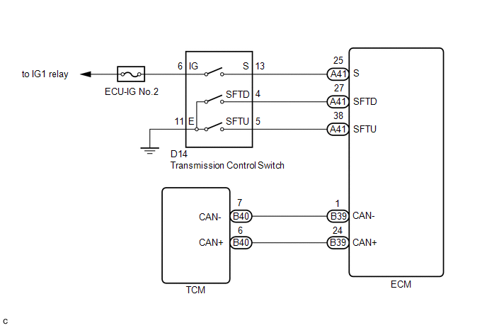
The engine control unit communicates with the TCM using the Controller Area Network (CAN).
If there is a problem in this communication, the TCM sets a DTC.
|
DTC No. |
DTC Detection Condition |
Trouble Area |
|---|---|---|
|
U0100 |
Following conditions are met for 1.25 seconds (1 trip detection logic):
|
|
MONITOR STRATEGY
|
Related DTCs |
U0100: Verify communication |
|
Required Sensors/Components (Main) |
TCM |
|
Required Sensors/Components (Related) |
- |
|
Frequency of Operation |
Continuous |
|
Duration |
1.25 seconds |
|
MIL Operation |
Immediate |
|
Sequence of Operation |
None |
TYPICAL ENABLING CONDITIONS
|
Monitor runs whenever following DTCs not present |
None |
|
Battery Voltage |
10.5 V or more |
|
Ignition Switch |
ON |
|
Starter |
OFF |
TYPICAL MALFUNCTION THRESHOLDS
|
Communication between TCM and ECM |
No communication |
WIRING DIAGRAM
CAUTION / NOTICE / HINT
NOTICE:
Perform the universal trip to clear permanent DTCs (See page
.gif) ).
).
HINT:
- Refer to inspection procedure for CAN communication system.
- If the CAN communication malfunctions, the TCM cannot receive the current data from the ECM. In this case, the freeze frame data output from the TCM has not been updated, so the data will not be useful for the inspection. However, reading the Data List as the first step in troubleshooting is effective to find malfunctions.
- The malfunction area can be checked using the Bus Check function on
the Techstream (See page ).
PROCEDURE
|
1. |
CHECK ECU TERMINAL VOLTAGE (+B AND E1 TERMINALS) |
|
(a) Disconnect the TCM connector. |
|
(b) Turn the ignition switch to ON.
(c) Measure the voltage according to the value(s) in the table below.
Standard Voltage:
|
Tester Connection |
Switch Condition |
Specified Condition |
|---|---|---|
|
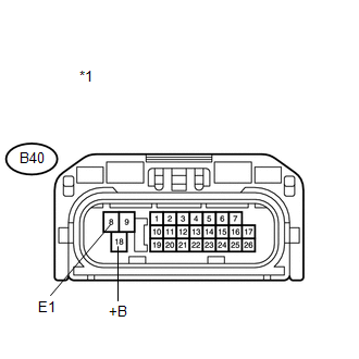
B40-18 (+B) - B40-8 (E1) |
Ignition switch ON |
9 to 14 V |
(d) Turn the ignition switch off.
(e) Measure the resistance according to the value(s) in the table below.
Standard Resistance:
|
Tester Connection |
Condition |
Specified Condition |
|---|---|---|
|
B40-8 (E1) - Body ground |
Always |
Below 1 Ω |
|
*1 |
Front view of wire harness connector (to TCM) |
| NG | .gif) |
REPAIR OR REPLACE HARNESS OR CONNECTOR |
|
.gif)
|
2. |
CHECK HARNESS AND CONNECTOR (TCM - ECM) |
|
(a) Disconnect the TCM connector. |
|
(b) Disconnect the ECM connector.
(c) Measure the resistance according to the value(s) in the table below.
Standard Resistance:
|
Tester Connection |
Condition |
Specified Condition |
|---|---|---|
|
B40-6 (CAN+) - B39-24 (CAN+) |
Always |
Below 1 Ω |
|
B40-7 (CAN-) - B39-1 (CAN-) |
Always |
Below 1 Ω |
|
B40-6 (CAN+) or B39-24 (CAN+) - Body ground or other terminals |
Always |
1 MΩ or higher |
|
B40-7 (CAN-) or B39-1 (CAN-) - Body ground or other terminals |
Always |
1 MΩ or higher |
|
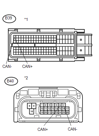
*1 |
Front view of wire harness connector (to ECM) |
|
*2 |
Front view of wire harness connector (to TCM) |
| NG | |
REPAIR OR REPLACE HARNESS OR CONNECTOR |
|
|
3. |
CHECK IF DTC OUTPUT RECURS |
(a) Connect the Techstream to the DLC3.
(b) Clear the DTCs.
(c) Replace the TCM.
HINT:
Replace the TCM with a TCM from a normally functioning vehicle of the same model.
(d) Start the engine.
(e) Read the DTCs.
|
Display (DTC Output) |
Proceed to |
|---|---|
|
U0100 |
A |
|
No DTC |
B |
| A | |
REPLACE ECM |
| B | |
REPLACE TCM |
 Pressure Control Solenoid "G" Electrical (Shift Solenoid Valve SL4) (P2810)
DESCRIPTION
Changing from 1st to 6th is performed by the TCM turning shift solenoid valves
SL1, SL2, SL3, SL4 and SL on and off. If an open or short circuit occurs in any
of the shift solenoid va ...
 Torque Converter Clutch Pressure Control Solenoid Control Circuit Electrical
(Shift Solenoid Valve SLU) (P2759)
Torque Converter Clutch Pressure Control Solenoid Control Circuit Electrical
(Shift Solenoid Valve SLU) (P2759)
DESCRIPTION
The amount of current flow to the solenoid is controlled by the duty ratio of
the TCM output signal. The higher the duty ratio becomes, the higher the lock-up
hydraulic pressure becom ...
Other materials about Toyota Venza:
Back Door Closer does not Operate
DESCRIPTION
When the back door closer does not operate, one of the following may be the cause:
1) improper fit of the back door, or a foreign object is stuck in the back door
or 2) initialization of the power back door ECU (power back door motor unit)*1, ...
Front Right Sensor Malfunction (C1AE4)
DESCRIPTION
The No. 1 ultrasonic sensor (front right sensor) is installed on the front bumper.
The ECU detects obstacles based on signals received from the No. 1 ultrasonic sensor
(front right sensor). If the No. 1 ultrasonic sensor (front right sensor) h ...
Inspection
INSPECTION
PROCEDURE
1. INSPECT FRONT POWER WINDOW REGULATOR MOTOR ASSEMBLY LH
(a) Apply positive (+) battery voltage to connector terminal 2 (B).
NOTICE:
Do not apply positive (+) battery voltage to any terminals other than
terminal 2 ...

0.1648