Toyota Venza: Open in Occupant Classification ECU Battery Positive Line (B1794)
DESCRIPTION
This circuit consists of the occupant classification ECU and power source circuit (battery, fuse and wire harness).
DTC B1794 is recorded when a malfunction is detected in the occupant classification ECU or power source circuit.
HINT:
If DTC B1794 is output after turning the ignition switch from off to ON and to off 50 times in a row when a malfunction occurs in the power circuit for the occupant classification system.
This DTC is output if a malfunction is detected even after being cleared unless the normal system code is input.
|
DTC No. |
DTC Detection Condition |
Trouble Area |
|---|---|---|
|
B1794 |
|
|
When DTC B1650/32 is detected as a result of troubleshooting for the airbag system, check the DTCs stored in the occupant classification ECU. When DTC B1794 is output, perform troubleshooting for the DTC.
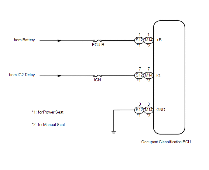
WIRING DIAGRAM
CAUTION / NOTICE / HINT
NOTICE:
Inspect the fuses for circuits related to this system before performing the following inspection procedure.
PROCEDURE
|
1. |
CHECK BATTERY |
(a) Measure the voltage of the battery.
Standard Voltage:
11 to 14 V
| NG | .gif) |
REPLACE BATTERY |
|
.gif)
|
2. |
CHECK WIRE HARNESS (SOURCE VOLTAGE) |
|
(a) Turn the ignition switch off. |
|
(b) Disconnect the cable from the negative (-) battery terminal.
(c) Disconnect the connector from the occupant classification ECU.
(d) Connect the cable to the negative (-) battery terminal.
(e) Turn the ignition switch to ON.
(f) Measure the voltage according to the value(s) in the table below.
Standard Voltage:
for Power Seat
|
Tester Connection |
Condition |
Specified Condition |
|---|---|---|
|
S12-1 (+B) - Body ground |
Always |
11 to 14 V |
|
S12-7 (IG) - Body ground |
Ignition switch ON |
11 to 14 V |
for Manual Seat
|
Tester Connection |
Condition |
Specified Condition |
|---|---|---|
|
M14-1 (+B) - Body ground |
Always |
11 to 14 V |
|
M14-7 (IG) - Body ground |
Ignition switch ON |
11 to 14 V |
(g) Turn the ignition switch off.
(h) Measure the resistance according to the value(s) in the table below.
Standard Resistance:
for Power Seat
|
Tester Connection |
Condition |
Specified Condition |
|---|---|---|
|
S12-3 (GND) - Body ground |
Always |
Below 1 Ω |
for Manual Seat
|
Tester Connection |
Condition |
Specified Condition |
|---|---|---|
|
M14-3 (GND) - Body ground |
Always |
Below 1 Ω |
|
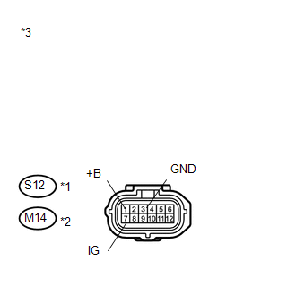
*1 |
for Power Seat |
|
*2 |
for Manual Seat |
|
*3 |
Front view of wire harness connector (to Occupant Classification ECU) |
| NG | |
REPLACE WIRE HARNESS |
|
|
3. |
CHECK DTC |
(a) Turn the ignition switch off.
(b) Disconnect the cable from the negative (-) battery terminal.
(c) Connect the connector to the occupant classification ECU.
(d) Connect the Techstream to the DLC3.
(e) Connect the cable to the negative (-) battery terminal.
(f) Turn the ignition switch to ON.
(g) Clear the DTCs stored in the occupant classification ECU (See page
.gif) ).
).
(h) Clear the DTCs stored in the center airbag sensor assembly (See page
).
(i) Turn the ignition switch off.
(j) Turn the ignition switch to ON, and wait for at least 10 seconds.
(k) Using the Techstream, check for DTCs of the occupant classification ECU (See
page ).
OK:
DTC B1794 is not output.
HINT:
Codes other than DTC B1794 may be output at this time, but they are not related to this check.
| OK | |
USE SIMULATION METHOD TO CHECK |
|
|
4. |
REPLACE OCCUPANT CLASSIFICATION ECU |
(a) Turn the ignition switch off.
(b) Disconnect the cable from the negative (-) battery terminal.
(c) Replace the occupant classification ECU (See page
).
|
|
5. |
PERFORM ZERO POINT CALIBRATION |
(a) Connect the cable to the negative (-) battery terminal.
(b) Connect the Techstream to the DLC3.
(c) Turn the ignition switch to ON.
(d) Using the Techstream, perform Zero Point Calibration (See page
).
OK:
"Zero Point Calibration is complete." is displayed.
|
|
6. |
PERFORM SENSITIVITY CHECK |
(a) Using the Techstream, perform Sensitivity Check (See page
).
Standard:
27 to 33 kg (59.5 to 72.8 lb)
| NEXT | |
END |
 Occupant Classification Sensor Power Supply Circuit Malfunction (B1793)
DESCRIPTION
The occupant classification sensor power supply circuit consists of the occupant
classification ECU and occupant classification sensors.
DTC B1793 is recorded when a malfunction is det ...
 Center Airbag Sensor Assembly Communication Circuit Malfunction (B1790)
DESCRIPTION
The center airbag sensor assembly communication circuit consists of the occupant
classification ECU and center airbag sensor assembly.
DTC B1790 is recorded when a malfunction is detec ...
Other materials about Toyota Venza:
Cruise Main Indicator Light Circuit
DESCRIPTION
The ECM detects a cruise control main switch signal and sends it to
the combination meter assembly through CAN. Then the CRUISE main indicator
light comes on.
The CRUISE main indicator light circuit uses CAN for communication.
...
If the engine will not start
If the engine still does not start after following the correct starting procedure
(, 175) or releasing the steering lock (, 176), confirm the following points.
- The engine will not start even if you are carrying the correct key.
One of the followi ...
Driver Side Power Window Auto Up / Down Function does not Operate with Power
Window Master Switch
DESCRIPTION
If the manual up/down function can be performed but the auto up/down function
cannot, then the fail-safe mode may be functioning.
If the power window initialization (See page
) has not been performed, the auto up/down function
will not oper ...

0.1296