Toyota Venza: Actuator Check
ACTUATOR CHECK
1. ACTUATOR CHECK
(a) Start the engine and warm it up.
(b) Perform the indicator check (See page .gif)
).
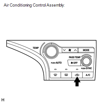
(c) Press the "Recirculation/Fresh" switch to perform the actuator check.
HINT:
Be sure to perform the actuator check after starting the engine.
Text in Illustration|
*1 |
Air Conditioning Control Assembly |
(d) As the actuator check is repeated from steps 1 to 10 at 1 second intervals, check the temperature and air flow visually and by hand.
.png)
HINT:
- The display blinks at 1 second intervals in the step operation.
- Press the "OFF" switch to finish panel diagnosis.
- Press the "AUTO" switch to enter sensor check mode.
|
*1 |
Accessory Meter Assembly (TFT) |
|
*2 |
Accessory Meter Assembly (LCD) |
|
*3 |
Display Code |
|
Step No. |
Display Code |
Condition |
||||
|---|---|---|---|---|---|---|
|
Blower Level |
Air Mix Damper |
Airflow Vent |
Air Inlet Damper |
Compressor |
||
|
1 |
0 |
0 |
0% open |
FACE |
FRESH |
off |
|
2 |
1 |
1 |
0% open |
FACE |
FRESH |
off |
|
3 |
2 |
17 |
0% open |
FACE |
RECIRCULATION/FRESH |
on |
|
4 |
3 |
17 |
0% open |
FACE |
RECIRCULATION |
on |
|
5 |
4 |
17 |
50% open |
B/L |
RECIRCULATION |
on |
|
6 |
5 |
17 |
50% open |
B/L |
RECIRCULATION |
on |
|
7 |
6 |
17 |
50% open |
FOOT |
FRESH |
on |
|
8 |
7 |
17 |
100% open |
FOOT-0 |
FRESH |
on |
|
9 |
8 |
17 |
100% open |
F/D |
FRESH |
on |
|
10 |
9 |
31 |
100% open |
DEF |
FRESH |
on |
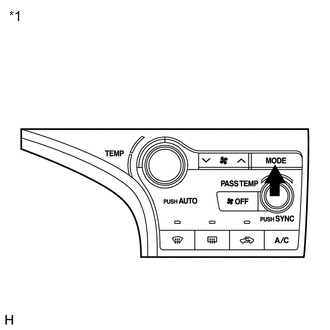
(e) If the steps are difficult to read because they change automatically, press the "MODE" switch to display the steps one at a time so that they can be read easily. The items are displayed step by step each time the "MODE" switch is pressed.
HINT:
- Press the "OFF" switch to finish panel diagnosis.
- Press the "Recirculation/Fresh" switch to enter sensor check mode.
|
*1 |
Air Conditioning Control Assembly |
 Diagnostic Trouble Code Chart
DIAGNOSTIC TROUBLE CODE CHART
HINT:
When the air conditioning system functions properly, DTC B1400/00 is output.
Air Conditioning System
DTC Code
Detection Item
Tr ...
 Lost Communication with ECM (U0100-U0142,U0155)
DESCRIPTION
DTC No.
DTC Detecting Condition
Trouble Area
U0100
No communication with ECM
CAN communication system
...
Other materials about Toyota Venza:
XM Tuner Antenna Disconnected (B15FE,B15FF)
DESCRIPTION
These DTCs are stored when a malfunction occurs in the roof antenna assembly
which is connected to the stereo component tuner assembly.
DTC No.
DTC Detection Condition
Trouble Area
B15FE
...
Headlight switch
The headlights can be operated manually or automatically.
Turning the end of the lever turns on the lights as follows.
Type A
The daytime running lights turn
on.
The headlights, parking lights, daytime running lights and so on turn on and
off auto ...
Internal Control Module Monitoring Processor Performance (P060A)
MONITOR DESCRIPTION
The main CPU and sub CPU of the ECM perform data communication between each other.
The main CPU monitors the communications and WDC pulses from the sub CPU. When the
signal malfunctions below are detected, the DTC is output.
...

0.1222