Toyota Venza: Relay
On-vehicle Inspection
ON-VEHICLE INSPECTION
PROCEDURE
1. FAN NO. 1 RELAY
|
(a) Remove the relay from the engine room relay block. |
|
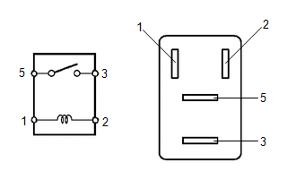
(b) Measure the resistance according to the value(s) in the table below.
Standard Resistance:
|
Tester Connection |
Condition |
Specified Condition |
|---|---|---|
|
3 - 5 |
Battery voltage is not applied between terminals 1 and 2 |
10 kΩ or higher |
|
3 - 5 |
Battery voltage is applied between terminals 1 and 2 |
Below 1 Ω |
- If the result is not as specified, replace the relay.
(c) Install the relay to the engine room relay block.
2. FAN NO. 2 RELAY
|
(a) Remove the relay from the engine room relay block. |
|
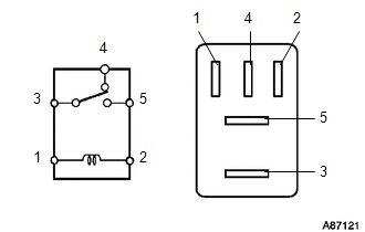
(b) Measure the resistance according to the value(s) in the table below.
Standard Resistance:
|
Tester Connection |
Condition |
Specified Condition |
|---|---|---|
|
3 - 4 |
Battery voltage is not applied between terminals 1 and 2 |
Below 1 Ω |
|
3 - 5 |
Battery voltage is not applied between terminals 1 and 2 |
10 kΩ or higher |
|
3 - 4 |
Battery voltage is applied between terminals 1 and 2 |
10 kΩ or higher |
|
3 - 5 |
Battery voltage is applied between terminals 1 and 2 |
Below 1 Ω |
- If the result is not as specified, replace the relay.
(c) Install the relay.
3. FAN NO. 3 RELAY
|
(a) Remove the relay from the engine room relay block. |
|
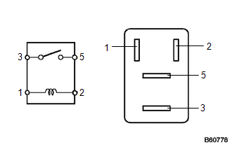
(b) Measure the resistance according to the value(s) in the table below.
Standard Resistance:
|
Tester Connection |
Condition |
Specified Condition |
|---|---|---|
|
3 - 5 |
Battery voltage is not applied between terminals 1 and 2 |
10 kΩ or higher |
|
3 - 5 |
Battery voltage is applied between terminals 1 and 2 |
Below 1 Ω |
- If the result is not as specified, replace the relay.
(c) Install the relay.
 Removal
REMOVAL
PROCEDURE
1. REMOVE NO. 1 ENGINE UNDER COVER
2. REMOVE NO. 2 ENGINE UNDER COVER
3. DRAIN ENGINE COOLANT
4. REMOVE COOL AIR INTAKE DUCT SEAL
5. REMOVE INLET AIR CLEANER ASSEMBLY
...
 Thermostat
...
Other materials about Toyota Venza:
Installation
INSTALLATION
PROCEDURE
1. INSTALL DRIVE MONITOR SWITCH
(a) Engage the 4 claws to install the drive monitor switch.
2. INSTALL RADIO AND DISPLAY RECEIVER ASSEMBLY WITH BRACKET (for Radio and Display
Type)
3. INSTALL NAVIGATION RECEIVER ASSEMBLY WITH B ...
Setting up the displays
Press the “SETUP” button while the
vehicle is stopped.
The “Custom Settings” screen is displayed on the multi-information display.
If left idle for approximately 10 seconds, the display will revert to the previous
screen.
Select “Display / ...
Fuel Sender Open Detected (B1500)
DESCRIPTION
This DTC is output when the combination meter assembly detects a fuel sender
gauge malfunction via the direct line.
DTC No.
DTC Detection Condition
Trouble Area
B1500
When either of t ...

0.1135