Toyota Venza: Rear Light Assembly
Components
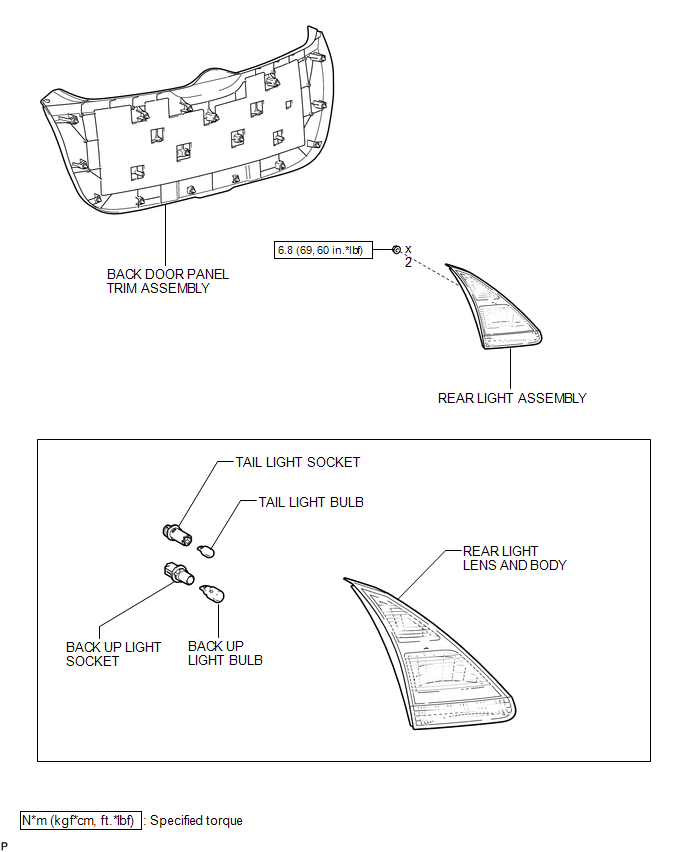
COMPONENTS
ILLUSTRATION
On-vehicle Inspection
ON-VEHICLE INSPECTION
PROCEDURE
1. INSPECT REAR LIGHT ASSEMBLY
|
(a) Disconnect the connector from the rear light assembly. |
|
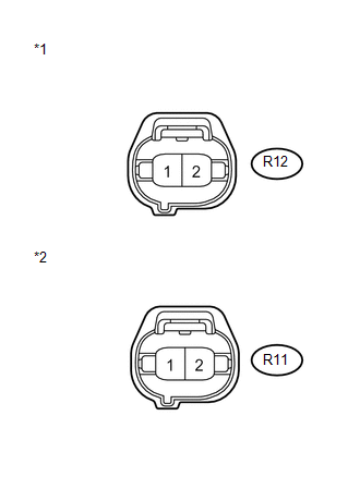
(b) Measure the voltage according to the value(s) in the table below.
Standard Voltage:
LH Side|
Tester Connection |
Condition |
Specified Condition |
|---|---|---|
|
R12-1 - R12-2 |
Light control switch in tail position |
11 to 14 V |
|
Light control switch off |
Below 1 V |
|
Tester Connection |
Condition |
Specified Condition |
|---|---|---|
|
R11-1 - R11-2 |
Light control switch in tail position |
11 to 14 V |
|
Light control switch off |
Below 1 V |
|
*1 |
Front view of wire harness connector (to Rear Light Assembly LH) |
|
*2 |
Front view of wire harness connector (to Rear Light Assembly RH) |
If the result is not as specified, repair or replace the wire harness or connector.
Disassembly
DISASSEMBLY
PROCEDURE
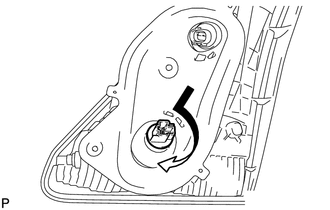
1. REMOVE TAIL LIGHT BULB
|
(a) Turn the tail light bulb and the tail light socket in the direction indicated by the arrow shown in the illustration and remove them as a unit. |
|
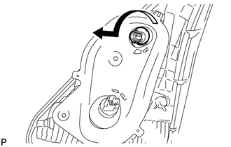
(b) Remove the tail light bulb from the tail light socket.
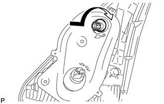
2. REMOVE BACK UP LIGHT BULB
|
(a) Turn the back up light bulb and the back up light socket in the direction indicated by the arrow shown in the illustration and remove them as a unit. |
|
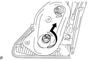
(b) Remove the back up light bulb from the back up light socket.
Removal
REMOVAL
PROCEDURE
1. REMOVE BACK DOOR PANEL TRIM ASSEMBLY
.gif)
2. REMOVE REAR LIGHT ASSEMBLY
|
(a) Disconnect the 2 connectors. |
|
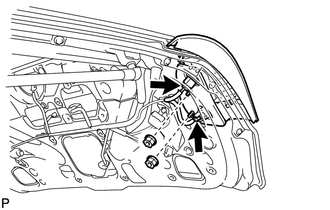
(b) Remove the 2 nuts.
|
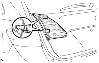
(c) Disengage the 2 pins and remove the rear light assembly. |
|
Installation
INSTALLATION
PROCEDURE
1. INSTALL REAR LIGHT ASSEMBLY
|
(a) Engage the 2 pins to install the rear light assembly. |
|
.png)
|
(b) Install the 2 nuts. Torque: 6.8 N·m {69 kgf·cm, 60 in·lbf} |
|
.png)
(c) Connect the 2 connectors.
2. INSTALL BACK DOOR PANEL TRIM ASSEMBLY
.gif)
Reassembly
REASSEMBLY
PROCEDURE
1. INSTALL BACK UP LIGHT BULB
(a) Install the back up light bulb to the back up light socket.
|
(b) Turn the back up light bulb to the back up light socket in the direction indicated by the arrow shown in the illustration to install them as a unit. |
|
2. INSTALL TAIL LIGHT BULB
(a) Install the tail light bulb to the tail light socket.
|
(b) Turn the tail light bulb to the tail light socket in the direction indicated by the arrow shown in the illustration to install them as a unit. |
|
 Installation
INSTALLATION
PROCEDURE
1. INSTALL REAR COMBINATION LIGHT ASSEMBLY
(a) Engage the guide and 2 pins, and install the rear combination light
assembly as shown in the illustration.
Te ...
 Relay
Relay
On-vehicle Inspection
ON-VEHICLE INSPECTION
PROCEDURE
1. INSPECT TAILLIGHT RELAY (TAIL)
(a) Remove the taillight relay from the main body ECU (driver side junction
block assembly) ...
Other materials about Toyota Venza:
Installation
INSTALLATION
PROCEDURE
1. INSTALL SPIRAL WITH SENSOR CABLE SUB-ASSEMBLY
(a) Install the spiral with sensor cable sub-assembly (See page
).
NOTICE:
Do not replace the spiral cable with the battery connected and the engine
switch on (IG).
...
Installation
INSTALLATION
CAUTION / NOTICE / HINT
HINT:
Perform "Inspection After Repair" after replacing the camshaft, No. 2 camshaft,
camshaft timing gear assembly, camshaft timing exhaust gear assembly or cylinder
head sub-assembly (See page ).
PROCED ...
Components
COMPONENTS
ILLUSTRATION
ILLUSTRATION
ILLUSTRATION
ILLUSTRATION
ILLUSTRATION
ILLUSTRATION
...

0.1746