Toyota Venza: Disassembly
DISASSEMBLY
PROCEDURE
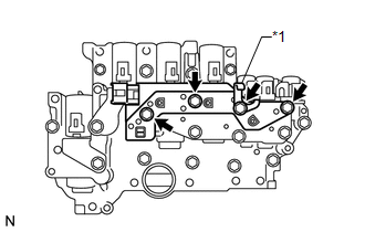
1. REMOVE TRANSMISSION WIRE
.gif)
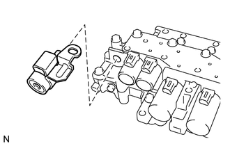
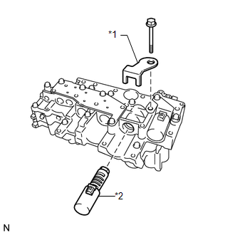
2. REMOVE ATF TEMPERATURE SENSOR ASSEMBLY
|
(a) Remove the 4 bolts, ATF temperature sensor assembly and clamp from the valve body assembly. Text in Illustration
|
|
|
(b) Remove the O-ring from the ATF temperature sensor assembly. Text in Illustration
|
|
.png)
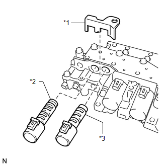
3. REMOVE SHIFT SOLENOID VALVE SL
|
(a) Remove the shift solenoid valve SL from the valve body assembly. |
|
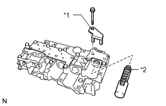
4. REMOVE SHIFT SOLENOID VALVE SLT
|
(a) Remove the lock plate and shift solenoid valve SLT from the valve body assembly. Text in Illustration
|
|
5. REMOVE SHIFT SOLENOID VALVE SLU
(a) Remove the shift solenoid valve SLU from the valve body assembly.
6. REMOVE SHIFT SOLENOID VALVE SL2
|
(a) Remove the bolt, lock plate and shift solenoid valve SL2 from the valve body assembly. Text in Illustration
|
|
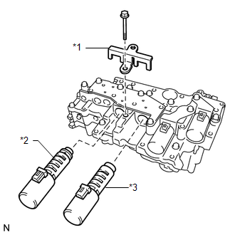
7. REMOVE SHIFT SOLENOID VALVE SL1
(a) Remove the shift solenoid valve SL1 from the valve body assembly.
8. REMOVE SHIFT SOLENOID VALVE SL3
|
(a) Remove the bolt, lock plate and shift solenoid valve SL3 from the valve body assembly. Text in Illustration
|
|
9. REMOVE SHIFT SOLENOID VALVE SL4
|
(a) Remove the bolt, lock plate and shift solenoid valve SL4 from the valve body assembly. Text in Illustration
|
|
 Components
COMPONENTS
ILLUSTRATION
ILLUSTRATION
...
 Removal
REMOVAL
PROCEDURE
1. REMOVE AUTOMATIC TRANSAXLE ASSEMBLY
HINT:
See the steps from "Remove Engine Assembly with transaxle" through "Remove Automatic
Transaxle Assembly" (See p ...
Other materials about Toyota Venza:
LVL Terminal Circuit
DESCRIPTION
By connecting terminals LVL and CG of the DLC3, the headlight leveling
ECU assembly initializes the height control sensor signal.
WIRING DIAGRAM
PROCEDURE
1.
CHECK HARNESS AND CONNECTOR (DLC3 - HEADLIGH ...
Unmatched Key Code (B2795)
DESCRIPTION
This DTC is stored when a key with a key code that has not been registered in
the ECU is inserted into the ignition key cylinder.
DTC No.
DTC Detection Condition
Trouble Area
B2795
Ke ...
Route cannot be Calculated
PROCEDURE
1.
SET DESTINATION
(a) Set another destination and check if the system can calculate the route correctly.
OK:
Route can be correctly calculated.
OK
END
NG
PROCEED T ...

0.1267