Toyota Venza: Removal
REMOVAL
PROCEDURE
1. REMOVE INSTRUMENT PANEL REINFORCEMENT ASSEMBLY WITH AIR CONDITIONING UNIT
(See page .gif) )
)
2. REMOVE COOL AIR INTAKE DUCT SEAL
3. REMOVE INLET NO. 2 AIR CLEANER
4. REMOVE AIR CLEANER CAP WITH HOSE
5. REMOVE AIR CLEANER CASE
6. REMOVE FRONT NO. 3 EXHAUST PIPE SUB-ASSEMBLY
7. SEPARATE MANIFOLD STAY
8. REMOVE EXHAUST MANIFOLD SUB-ASSEMBLY RH
9. REMOVE EXHAUST MANIFOLD TO HEAD GASKET
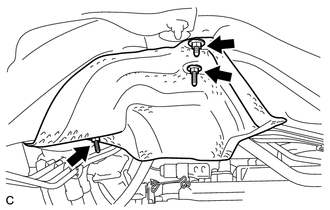
10. REMOVE FRONT NO. 1 FLOOR HEAT INSULATOR
|
(a) Remove the 3 nuts and front No. 1 floor heat insulator. |
|
11. REMOVE TRANSMISSION CONTROL CABLE ASSEMBLY
|
(a) Remove the clip and disconnect the transmission control cable assembly from the No. 1 control cable bracket. |
|
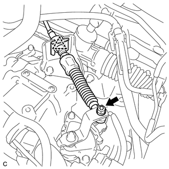
(b) Remove the nut and transmission control cable assembly from the transmission control shaft lever.
|
(c) Disconnect the transmission control cable assembly from the No. 2 transmission control cable bracket. |
|
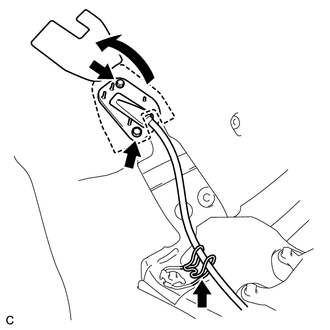
(d) Turn back the carpet.
(e) Remove the 2 bolts and pull out the transmission control cable assembly from the body.
 Components
COMPONENTS
ILLUSTRATION
ILLUSTRATION
...
 Adjustment
ADJUSTMENT
PROCEDURE
1. INSPECT SHIFT LEVER POSITION
(a) When moving the lever from P to R with the ignition switch ON and the brake
pedal depressed, make sure that the shift lever moves smoothly ...
Other materials about Toyota Venza:
Inspection
INSPECTION
PROCEDURE
1. INSPECT PAD LINING THICKNESS
(a) Using a ruler, measure the pad lining thickness.
Text in Illustration
*1
Ruler
Standard thickness of a new pad:
12.0 mm (0.472 ...
Installation
INSTALLATION
PROCEDURE
1. INSTALL YAW RATE AND ACCELERATION SENSOR
(a) Install the yaw rate and acceleration sensor to the bracket with
the 2 nuts.
Torque:
5.0 N·m {51 kgf·cm, 44 in·lbf}
...
Cup holders
► Front
► Rear
Pull down the armrest and open the lid.
- Adjusting size of the front cup holder
Remove the adapter.
CAUTION
- Items unsuitable for the cup holder
Do not place anything other than cups or aluminum cans in the ...

0.1448