Toyota Venza: Inspection
INSPECTION
PROCEDURE
1. INSPECT STARTER ASSEMBLY
NOTICE:
These tests must be performed within 3 to 5 seconds to avoid burning out the coil.
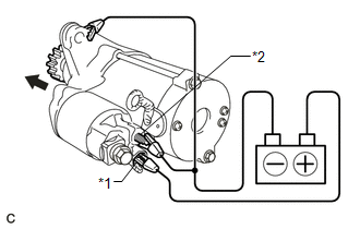
(a) Perform a pull-in test.
(1) Remove the nut and disconnect the lead wire from terminal C.
|
(2) Connect the battery to the magnetic switch as shown in the illustration. Check that the clutch pinion gear extends. Text in Illustration
If the clutch pinion gear does not move, replace the magnetic switch assembly. |
|
|
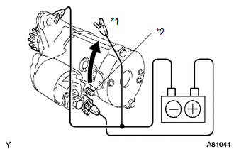
(b) Perform a hold-in test. (1) While maintaining the battery connections of the pull-in test above, disconnect the negative (-) lead from terminal C. Check that the pinion gear remains extended. Text in Illustration
If the clutch pinion gear returns inward, replace the magnetic switch assembly. |
|
|
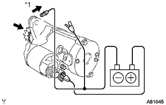
(c) Perform a clutch pinion gear return test. (1) Disconnect the negative (-) lead from the starter body. Check that the clutch pinion gear returns. If the clutch pinion gear does not return, replace the magnetic switch assembly. Text in Illustration
|
|
|
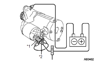
(d) Perform a no-load performance test. Text in Illustration
(1) Connect the lead wire to terminal C with the nut. Make sure that the lead is not grounded. Torque: 10 N·m {102 kgf·cm, 7 ft·lbf} (2) Clamp the starter in a vise. (3) Connect the battery and an ammeter to the starter as shown in the illustration. (4) Check that the starter rotates smoothly and steadily while the pinion gear is moving out. Then measure the current. Standard current: 90 A or less at 11.5 V If the result is not as specified, repair or replace the starter assembly. |
|
2. INSPECT MAGNETIC SWITCH ASSEMBLY
|
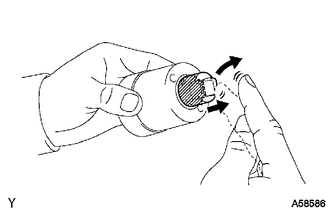
(a) Check the plunger. (1) Push in the plunger and check that it returns quickly to its original position. If necessary, replace the magnetic switch assembly. |
|
|
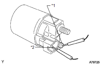
(b) Check if the pull-in coil has an open circuit. Text in Illustration
(1) Measure the resistance between terminals 50 and C. Standard resistance: Below 1 Ω If the result is not as specified, replace the magnetic switch assembly. |
|
|
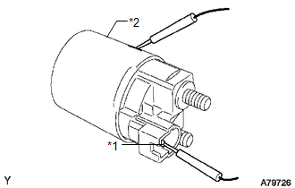
(c) Check if the hold-in coil has an open circuit. Text in Illustration
(1) Measure the resistance between terminal 50 and the switch body. Standard resistance: Below 2 Ω If the result is not as specified, replace the magnetic switch assembly. |
|
3. INSPECT STARTER ARMATURE ASSEMBLY
HINT:
If these is no continuity between any segments, replace the starter armature assembly.
(a) Check the commutator for contamination and burns on its surface.
If the surface is dirty or burnt, correct it with sandpaper (No. 400) or a lathe.
|
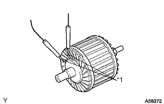
(b) Check if the commutator has an open circuit. Text in Illustration
(1) Measure the resistance between the segments of the commutator. Standard resistance: Below 1 Ω If the result is not as specified, replace the armature assembly. |
|
|
(c) Check if the commutator is grounded. Text in Illustration
(1) Measure the resistance between the commutator and armature coil core. Standard resistance: 10 kΩ or higher If the result is not as specified, replace the armature assembly. |
|
|
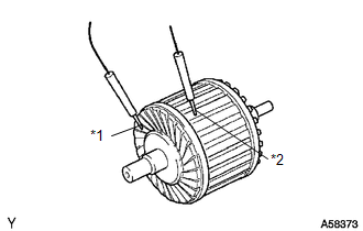
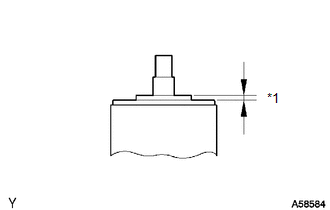
(d) Using a vernier caliper, measure the commutator length. Text in Illustration
Standard length: 3.1 to 3.8 mm (0.122 to 0.149 in.) Maximum length: 3.8 mm (0.149 in.) If the length is greater than the maximum, replace the starter armature assembly. |
|
4. INSPECT STARTER COMMUTATOR END FRAME ASSEMBLY
|
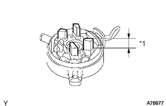
(a) Using a vernier caliper, measure the brush length. Text in Illustration
Standard length: 4.0 to 9.0 mm (0.158 to 0.354 in.) Minimum length: 4.0 mm (0.158 in.) If the length is less than the minimum, replace the end frame assembly. |
|
|
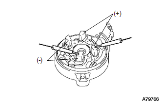
(b) Check the brush insulation. (1) Measure the resistance between the positive (+) and negative (-) brushes. Standard resistance: 10 kΩ or higher If the result is not as specified, replace the end frame assembly. |
|
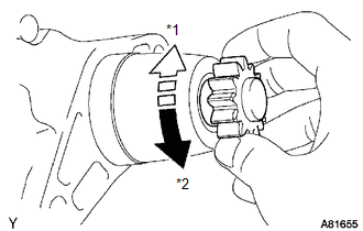
5. INSPECT STARTER CLUTCH
Text in Illustration
(a) Rotate the clutch pinion gear counterclockwise and check that it turns freely. Try to rotate the clutch pinion gear clockwise and check that it locks. If necessary, replace the starter drive housing assembly. |
|
 Disassembly
DISASSEMBLY
PROCEDURE
1. REMOVE MAGNETIC SWITCH ASSEMBLY
(a) Remove the nut and disconnect the lead wire from the magnetic switch.
...
 Reassembly
REASSEMBLY
CAUTION / NOTICE / HINT
HINT:
Use high-temperature grease to lubricate the bearings, gears and return spring
when assembling the starter.
PROCEDURE
1. INSTALL PLANETARY GEAR
...
Other materials about Toyota Venza:
Installation
INSTALLATION
PROCEDURE
1. INSTALL SEPARATE TYPE FRONT SEATBACK COVER
(a) Using a tacker, install the separate type front seatback heater to
the end of the separate type front seatback cover with 12 new tack pins.
NOTICE:
Be careful not ...
Vehicle Speed Signal Circuit between Radio Receiver and Combination Meter
DESCRIPTION
for Automatic Sound Levelizer (ASL):
This circuit is necessary for the Automatic Sound Levelizer (ASL) built
into the radio and display receiver assembly.
The Automatic Sound Levelizer (ASL) function automatically adjusts the
a ...
Reassembly
REASSEMBLY
CAUTION / NOTICE / HINT
HINT:
Perform "Inspection After Repair" after replacing the cylinder head sub-assembly
(See page ).
PROCEDURE
1. INSTALL SPARK PLUG TUBE
HINT:
When using a new cylinder head, the spark plug tubes must be r ...

0.1271