Toyota Venza: Removal
REMOVAL
PROCEDURE
1. REMOVE UPPER CONSOLE PANEL SUB-ASSEMBLY (w/o Seat Heater System)
.gif)
2. REMOVE UPPER CONSOLE PANEL SUB-ASSEMBLY (w/ Seat Heater System)
3. REMOVE NO. 2 CONSOLE BOX CARPET
4. REMOVE CONSOLE BOX ASSEMBLY
5. REMOVE AIR CONDITIONING CONTROL ASSEMBLY
6. REMOVE FRONT DOOR SCUFF PLATE RH
7. REMOVE COWL SIDE TRIM SUB-ASSEMBLY RH
8. REMOVE NO. 2 INSTRUMENT PANEL UNDER COVER SUB-ASSEMBLY
9. REMOVE LOWER INSTRUMENT PANEL SUB-ASSEMBLY
10. REMOVE SHIFT LEVER KNOB SUB-ASSEMBLY
11. REMOVE POSITION INDICATOR HOUSING ASSEMBLY
12. REMOVE CONSOLE BOX SUB-ASSEMBLY
13. REMOVE NO. 2 INSTRUMENT PANEL SPEAKER PANEL SUB-ASSEMBLY
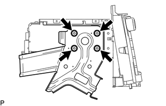
14. REMOVE RADIO AND DISPLAY RECEIVER ASSEMBLY WITH BRACKET
|
(a) Remove the 4 bolts. |
|
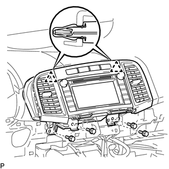
(b) Disengage the 2 clips.
(c) Disconnect each connector and remove the radio and display receiver assembly with bracket.
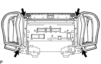
15. REMOVE INSTRUMENT CLUSTER CENTER FINISH PANEL SUB-ASSEMBLY
|
(a) Remove the 4 screws. |
|
|
(b) Disengage the 4 claws and remove the instrument cluster center finish panel sub-assembly. |
|
16. REMOVE STEREO COMPONENT TUNER ASSEMBLY WITH WIRE (w/ Satellite Radio)
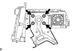
17. REMOVE NO. 1 RADIO RECEIVER BRACKET
|
(a) Remove the 4 screws and No. 1 radio receiver bracket. |
|
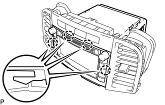
18. REMOVE NO. 2 RADIO RECEIVER BRACKET
|
(a) Remove the 4 screws and No. 2 radio receiver bracket. |
|
19. REMOVE RADIO AND DISPLAY RECEIVER ASSEMBLY
 Components
COMPONENTS
ILLUSTRATION
ILLUSTRATION
ILLUSTRATION
ILLUSTRATION
...
 Installation
INSTALLATION
PROCEDURE
1. INSTALL RADIO AND DISPLAY RECEIVER ASSEMBLY
2. INSTALL NO. 2 RADIO RECEIVER BRACKET
(a) Install the No. 2 radio receiver bracket with the 4 screws.
Torque:
5.0 N·m {5 ...
Other materials about Toyota Venza:
Engine Immobiliser System Malfunction (B2799)
DESCRIPTION
This DTC is stored when one of the following occurs: 1) the ECM detects an error
in its own communication with the certification ECU (smart key ECU assembly); 2)
the ECM detects an error in the communication lines; or 3) the ECU communication ...
Installation
INSTALLATION
PROCEDURE
1. INSTALL FRONT POWER SEAT LUMBAR SWITCH
(a) Install the front power seat lumbar switch with the 2 screws.
2. INSTALL FRONT SEAT CUSHION SHIELD ASSEMBLY
3. INSTALL SLIDE ...
Radio Antenna
Components
COMPONENTS
ILLUSTRATION
ILLUSTRATION
Installation
INSTALLATION
PROCEDURE
1. INSTALL RADIO ANTENNA ASSEMBLY
(a) Engage the 2 claws to install the radio antenna assembly.
(b) Place the antenna cord in the cutout of the ante ...

0.1257