Toyota Venza: Removal
REMOVAL
PROCEDURE
1. DISCONNECT CABLE FROM NEGATIVE BATTERY TERMINAL
NOTICE:
When disconnecting the cable, some systems need to be initialized after the cable
is reconnected (See page .gif) ).
).
2. REMOVE UPPER CONSOLE PANEL SUB-ASSEMBLY (w/o Seat Heater System)
3. REMOVE UPPER CONSOLE PANEL SUB-ASSEMBLY (w/ Seat Heater System)
4. REMOVE NO. 2 CONSOLE BOX CARPET
5. REMOVE CONSOLE BOX ASSEMBLY
6. REMOVE AIR CONDITIONING CONTROL ASSEMBLY
7. REMOVE FRONT DOOR SCUFF PLATE LH
8. REMOVE COWL SIDE TRIM SUB-ASSEMBLY LH
9. REMOVE LOWER NO. 1 INSTRUMENT PANEL FINISH PANEL
10. REMOVE FRONT DOOR SCUFF PLATE RH
11. REMOVE COWL SIDE TRIM SUB-ASSEMBLY RH
12. REMOVE NO. 2 INSTRUMENT PANEL UNDER COVER SUB-ASSEMBLY
13. REMOVE LOWER INSTRUMENT PANEL SUB-ASSEMBLY
14. REMOVE SHIFT LEVER KNOB SUB-ASSEMBLY
15. REMOVE POSITION INDICATOR HOUSING ASSEMBLY
16. REMOVE CONSOLE BOX SUB-ASSEMBLY
17. REMOVE SHIFT LEVER ASSEMBLY
(a) Move the shift lever to N.
|
(b) Disconnect the 2 connectors. |
|
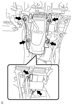
(c) Remove the 4 nuts and shift lever assembly.
|
(d) Disconnect the end of the transmission control cable assembly from the shift lever assembly. |
|
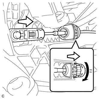
(e) Turn the lock nut counterclockwise. While holding the lock nut, disconnect the transmission control cable from the shift lever retainer.
 Disassembly
DISASSEMBLY
PROCEDURE
1. REMOVE POSITION INDICATOR HOUSING SUB-ASSEMBLY
(a) Remove the shift lever cap from the position indicator housing sub-assembly.
(b) Disengage the 4 claws and re ...
 Inspection
INSPECTION
PROCEDURE
1. INSPECT SHIFT LOCK CONTROL UNIT ASSEMBLY (w/o Smart Key System)
(a) Measure the voltage according to the value(s) in the table below.
Text in Illustration
...
Other materials about Toyota Venza:
Differential System
Precaution
PRECAUTION
Before disassembly, clean the outside of the differential assembly and
remove any sand or mud to prevent it from entering the inside of the assembly
during disassembly and installation.
When removing an installed pa ...
Portable Player cannot be Connected Manually/Automatically
CAUTION / NOTICE / HINT
HINT:
Some versions of "Bluetooth" compatible audio players may not function properly,
or the functions may be limited using the navigation receiver assembly, even if
the portable audio player itself can play files (See ...
Differential Mount Cushion
Components
COMPONENTS
ILLUSTRATION
Installation
INSTALLATION
PROCEDURE
1. INSTALL REAR NO. 1 DIFFERENTIAL MOUNT CUSHION
(a) Using SST, install a new rear No. 1 differential mount cushion.
Text in Illustration
*1
Protrusion ...

0.1332