Toyota Venza: Disassembly
DISASSEMBLY
PROCEDURE
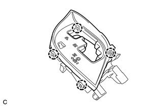
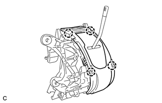
1. REMOVE POSITION INDICATOR HOUSING SUB-ASSEMBLY
(a) Remove the shift lever cap from the position indicator housing sub-assembly.
|
(b) Disengage the 4 claws and remove the position indicator housing sub-assembly. |
|
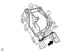
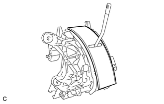
2. REMOVE POSITION INDICATOR LIGHT GUIDE
|
(a) Disengage the 4 claws and remove the position indicator connector and position indicator light guide. |
|
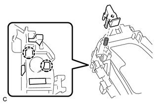
3. REMOVE SHIFT LOCK RELEASE BUTTON
|
(a) Disengage the 2 claws to remove the shift lock release button and compression spring. |
|
4. REMOVE INDICATOR LIGHT WIRE SUB-ASSEMBLY
|
(a) Remove the indicator light wire sub-assembly from the position indicator light guide. |
|
5. REMOVE POSITION INDICATOR LIGHT BULB
(a) Remove the position indicator light cap from the position indicator light bulb.
(b) Remove the position indicator light bulb from the indicator light wire sub-assembly.
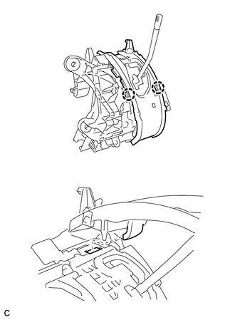
6. REMOVE UPPER POSITION INDICATOR HOUSING
|
(a) Detach the 4 claws and remove the upper position indicator housing from the lower position indicator housing. |
|
7. REMOVE POSITION INDICATOR SLIDE COVER
|
(a) Remove the position indicator slide cover from the lower position indicator housing. |
|
8. REMOVE NO. 2 POSITION INDICATOR SLIDE COVER
(a) Remove the No. 2 position indicator slide cover from the position indicator slide cover.
9. REMOVE LOWER POSITION INDICATOR HOUSING
|
(a) Detach the 2 claws and remove the lower position indicator housing from the shift lock control unit assembly. |
|
10. REMOVE SHIFT LOCK CONTROL COMPUTER SUB-ASSEMBLY
|
(a) Disconnect the connector from the shift lock control computer sub-assembly. |
|
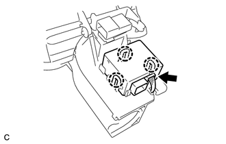
(b) Detach the 3 claws and remove the shift lock control computer sub-assembly.
 On-vehicle Inspection
ON-VEHICLE INSPECTION
PROCEDURE
1. INSPECT SHIFT LOCK CONTROL UNIT ASSEMBLY
(a) Inspect the shift lock operation.
(1) Move the shift lever to P.
(2) Turn the ignition switch off.
(3) Check that ...
 Removal
REMOVAL
PROCEDURE
1. DISCONNECT CABLE FROM NEGATIVE BATTERY TERMINAL
NOTICE:
When disconnecting the cable, some systems need to be initialized after the cable
is reconnected (See page ).
2. RE ...
Other materials about Toyota Venza:
Reassembly
REASSEMBLY
PROCEDURE
1. BEARING POSITION
(a) Check each bearing position and installation direction.
Mark
Front Race Diameter
Inside / Outside mm (in.)
Thrust Bearing Diameter
Inside / Outside mm (in.)
...
Stop Light Switch
Components
COMPONENTS
ILLUSTRATION
Removal
REMOVAL
PROCEDURE
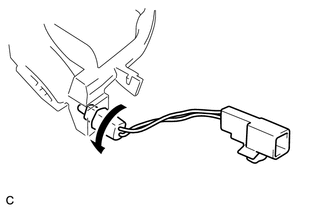
1. REMOVE STOP LIGHT SWITCH ASSEMBLY
(a) Disconnect the connector.
(b) Turn the stop light switch assembly countercl ...
Slide Sensor Malfunction (B2650)
DESCRIPTION
When the position control ECU and switch assembly does not receive a sensor signal
despite forward or backward movement of seat by power seat motor operation, this
DTC is output.
DTC Code
DTC Detection Condition
...

0.1579