Toyota Venza: Removal
REMOVAL
CAUTION / NOTICE / HINT
NOTICE:
If automatic transaxle assembly parts are replaced, refer to Parts Replacement
Compensation Table to determine if any additional operations are necessary (See
page .gif) ).
).
PROCEDURE
1. REMOVE ENGINE ASSEMBLY WITH TRANSAXLE
HINT:
See the steps from "Recover Refrigerant From Refrigeration System" through "Remove
Engine Assembly with Transaxle" (See page ).
2. DISCONNECT FRONT CROSSMEMBER SUB-ASSEMBLY
3. REMOVE STARTER ASSEMBLY
4. REMOVE MANIFOLD STAY
5. REMOVE TCM
6. SEPARATE WIRE HARNESS
|
(a) Remove the 2 bolts and disconnect the 2 wire harnesses from the automatic transaxle assembly. |
|
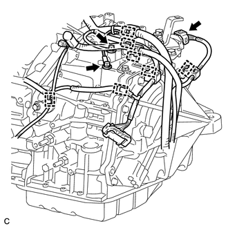
(b) Separate the park/neutral position switch assembly connector and 7 wire harness clamps from the automatic transaxle assembly.
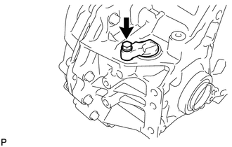
7. REMOVE FLEXIBLE HOSE BRACKET SUB-ASSEMBLY
|
(a) Remove the bolt and flexible hose bracket sub-assembly from the camshaft housing sub-assembly LH. |
|
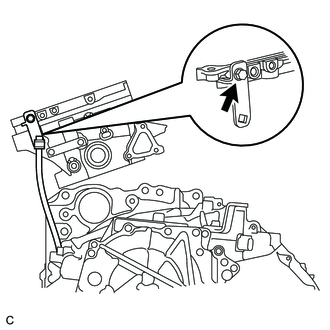
(b) Remove the No. 1 breather plug (ATM) from the flexible hose bracket sub-assembly.
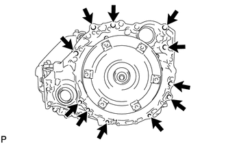
8. REMOVE AUTOMATIC TRANSAXLE ASSEMBLY
|
(a) Remove the 11 bolts and automatic transaxle assembly from the engine assembly. NOTICE: To prevent damage to the 2 knock pins, do not pry between the automatic transaxle assembly and engine assembly. |
|
9. REMOVE TORQUE CONVERTER ASSEMBLY
(a) Remove the torque converter assembly from the automatic transaxle assembly.
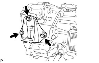
10. REMOVE FRONT ENGINE MOUNTING BRACKET
|
(a) Remove the 3 bolts and front engine mounting bracket from the automatic transaxle assembly. |
|
11. REMOVE WIRE HARNESS CLAMP BRACKET
|
(a) Remove the 4 bolts and 4 wire harness clamp brackets from the automatic transaxle assembly. |
|
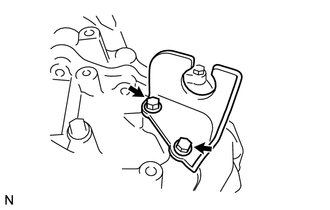
12. REMOVE NO. 1 TRANSMISSION CONTROL CABLE BRACKET
|
(a) Remove the 2 bolts and No. 1 transmission control cable bracket from the automatic transaxle assembly. |
|
13. REMOVE SPEEDOMETER DRIVEN HOLE (ATM) COVER SUB-ASSEMBLY
|
(a) Remove the bolt and speedometer driven hole (ATM) cover sub-assembly from the automatic transaxle assembly. |
|
(b) Remove the O-ring from the speedometer driven hole (ATM) cover sub-assembly.
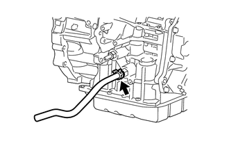
14. REMOVE NO. 1 OIL COOLER OUTLET HOSE
|
(a) Slide the clip and disconnect the No. 1 oil cooler outlet hose from the automatic transaxle assembly. |
|
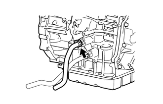
15. REMOVE NO. 1 OIL COOLER INLET HOSE
|
(a) Slide the clip and disconnect the No. 1 oil cooler inlet hose from the automatic transaxle assembly. |
|
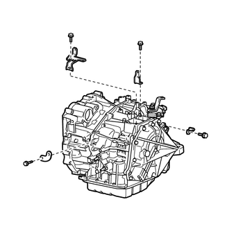
 Components
COMPONENTS
ILLUSTRATION
ILLUSTRATION
ILLUSTRATION
...
 Installation
INSTALLATION
PROCEDURE
1. INSPECT TORQUE CONVERTER ASSEMBLY
2. INSTALL TORQUE CONVERTER ASSEMBLY
(a) Engage the splines of the input shaft and turbine runner.
...
Other materials about Toyota Venza:
Customize Parameters
CUSTOMIZE PARAMETERS
1. CUSTOMIZE METER / GAUGE SYSTEM
(a) Customizing with the Techstream
(1) Connect the Techstream to the DLC3.
(2) Turn the ignition switch to ON.
(3) Turn the Techstream on.
(4) Enter the following menus: Customize Setting / Warning. ...
Certification ECU Vehicle Information Reading/Writing Process Malfunction (B15F7)
DESCRIPTION
This DTC is stored when items controlled by the certification ECU (smart key
ECU assembly) cannot be customized via the navigation system vehicle customization
screen.
HINT:
The certification ECU (smart key ECU assembly) controls the smart k ...
Evaporator Temperature Sensor Circuit (B1413/13)
DESCRIPTION
The evaporator temperature sensor is installed on the evaporator in the air conditioning
unit to detect the cooled air temperature that has passed through the evaporator
and to control the air conditioning. It sends appropriate signals to the ...

0.1582