Toyota Venza: Reassembly
REASSEMBLY
PROCEDURE
1. INSTALL FUEL PUMP ASSEMBLY WITH FILTER
HINT:
Perform "Inspection After Repair" after replacing the fuel pump (See page
.gif) ).
).
|
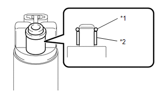
(a) Apply gasoline to a new O-ring. Then install the O-ring and spacer to the fuel pump. Text in Illustration
|
|
|
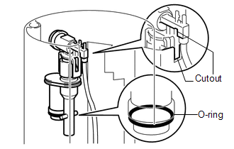
(b) Engage the 5 claws on the fuel filter and install the fuel pump assembly with filter. NOTICE:
|
|
.png)
2. INSTALL FUEL FILTER ASSEMBLY
|
(a) Apply gasoline to a new O-ring and install it to the jet pump. Text in Illustration
|
|
.png)
|
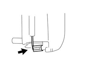
(b) Install the jet pump to the sub-tank as shown in the illustration. |
|
|
(c) Connect the jet pump nozzle to the fuel sub-tank. |
|
|
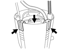
(d) Install the fuel filter to the sub-tank and attach the 2 claws. |
|
|
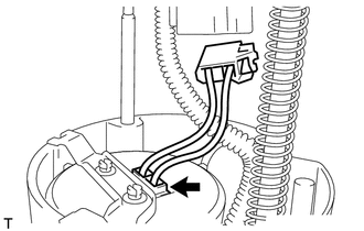
(e) Connect the fuel pump connector to the fuel pump. |
|
3. INSTALL FUEL SUCTION PLATE SUB-ASSEMBLY
(a) Install the spring to the fuel suction plate shaft.
(b) Install the fuel suction plate to the sub-tank.
|
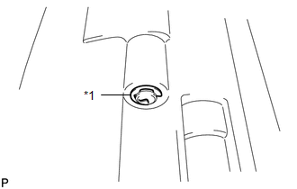
(c) Install a new E-ring. Text in Illustration
|
|
|
(d) Connect the fuel pump connector to the fuel suction plate. |
|
.png)
4. INSTALL FUEL SENDER GAUGE
 Inspection
INSPECTION
PROCEDURE
1. INSPECT FUEL PUMP ASSEMBLY WITH FILTER
(a) Inspect fuel pump resistance.
(1) Measure the resistance according to the value(s) in the table below.
Standard Resistance:
...
 Installation
INSTALLATION
PROCEDURE
1. INSTALL FUEL SUCTION TUBE ASSEMBLY WITH PUMP AND GAUGE
(a) Install a new fuel suction tube set gasket onto the fuel tank.
(b) Connect the fuel tube with the cl ...
Other materials about Toyota Venza:
Clearance Warning Ecu
Components
COMPONENTS
ILLUSTRATION
Removal
REMOVAL
PROCEDURE
1. REMOVE FRONT DOOR SCUFF PLATE RH
2. REMOVE COWL SIDE TRIM SUB-ASSEMBLY RH
3. REMOVE NO. 2 INSTRUMENT PANEL UNDER COVER SUB-ASSEMBLY
4. REMOVE LOWER INSTRUMENT PANEL SUB-ASS ...
Removal
REMOVAL
PROCEDURE
1. REMOVE NO. 1 FLOOR UNDER COVER
(a) Disengage the 4 nuts and clip, and remove the No. 1 floor under cover.
Text in Illustration
Nut (attached to under cover)
HINT:
Rotate the clip to disengage it. The 4 ...
Lost Communication with Gateway Module (Power Management2) (U1002)
DESCRIPTION
The power management control ECU will store this DTC when no signals
can be received from the ECUs that have been memorized as those that are
connected to the power management bus.
When the power management control ECU receives ...

0.1146