Toyota Venza: Installation
INSTALLATION
PROCEDURE
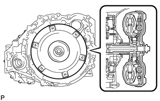
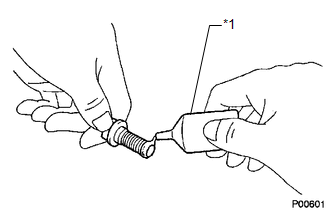
1. INSPECT TORQUE CONVERTER ASSEMBLY
.gif)
2. INSTALL TORQUE CONVERTER ASSEMBLY
|
(a) Engage the splines of the input shaft and turbine runner. |
|
|
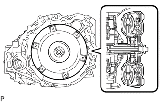
(b) Engage the splines of the stator shaft and the stator while turning the torque converter assembly. HINT: If the stator shaft splines are difficult to engage with the stator splines, move the torque converter assembly back approximately 10 mm and engage the splines while rotating the torque converter assembly. |
|
|
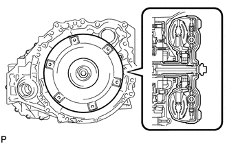
(c) Turn the torque converter assembly to engage the key of the oil pump drive gear into the slot on the torque converter assembly. |
|
|
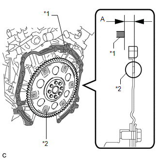
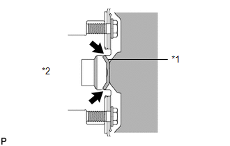
(d) Using a vernier caliper and a straightedge, measure dimension "A" between the automatic transaxle assembly fitting surface of the engine assembly*1 and the torque converter assembly fitting surface of the drive plate*2. (#) NOTICE: Make sure to deduct the thickness of the straightedge. |
|
|
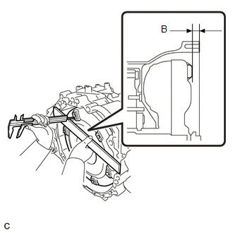
(e) Using a vernier caliper and a straightedge, measure dimension "B" shown in the illustration and check that "B" is greater than "A" (measured in step (#)). Standard: A + 1 mm (0.0394 in.) or more NOTICE:
HINT: If a U660E is used with a 2GR-FE, the standard installation depth is 14 mm (0.551 in.) or more. |
|
3. INSTALL NO. 1 OIL COOLER INLET HOSE
|
(a) Connect the No. 1 oil cooler inlet hose and slide the clip to secure it. |
|
.png)
4. INSTALL NO. 1 OIL COOLER OUTLET HOSE
|
(a) Connect the No. 1 oil cooler outlet hose and slide the clip to secure it. |
|
.png)
5. INSTALL SPEEDOMETER DRIVEN HOLE (ATM) COVER SUB-ASSEMBLY
(a) Apply ATF to a new O-ring and install it to the speedometer driven hole (ATM) cover sub-assembly.
|
(b) Install the speedometer driven hole (ATM) cover sub-assembly to the automatic transaxle assembly with the bolt. Torque: 5.5 N·m {56 kgf·cm, 49 in·lbf} |
|
.png)
6. INSTALL NO. 1 TRANSMISSION CONTROL CABLE BRACKET
|
(a) Install the No. 1 transmission control cable bracket to the automatic transaxle assembly with the 2 bolts. Torque: 12 N·m {122 kgf·cm, 9 ft·lbf} |
|
.png)
7. INSTALL WIRE HARNESS CLAMP BRACKET
|
(a) Install the 4 wire harness clamp brackets to the automatic transaxle assembly with the 4 bolts. Torque: 8.4 N·m {86 kgf·cm, 74 in·lbf} |
|
.png)
8. INSTALL FRONT ENGINE MOUNTING BRACKET
|
(a) Install the front engine mounting bracket to the automatic transaxle assembly with the 3 bolts. Torque: 64 N·m {653 kgf·cm, 47 ft·lbf} |
|
.png)
9. INSTALL AUTOMATIC TRANSAXLE ASSEMBLY
|
(a) Apply clutch spline grease to the round of the crankshaft contact surface of the torque converter assembly centerpiece. Text in Illustration
Clutch Spline Grease: Toyota Genuine Clutch Spline Grease or equivalent Maximum Spread: About 1 g (0.0353 oz.) Centerpiece |
|
|
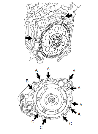
(b) While keeping the engine assembly and automatic transaxle assembly in a horizontal position, align the 2 knock pins with each hole on the automatic transaxle assembly and tighten the 11 bolts shown in the illustration. Torque: Bolt (A) : 64 N·m {653 kgf·cm, 47 ft·lbf} Bolt (B) : 64 N·m {653 kgf·cm, 47 ft·lbf} Bolt (C) : 43 N·m {439 kgf·cm, 32 ft·lbf} NOTICE:
HINT: Bolt Length:
|
|
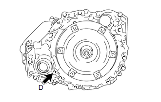
(c) Clean and degrease the bolt and the installation hole in the automatic transaxle assembly.
|
(d) Apply adhesive to 2 or 3 threads on the ends of the bolt. Text in Illustration
Adhesive: Toyota Genuine Adhesive 1344, Three Bond 1344 or equivalent |
|
|
(e) Install the bolt. Torque: Bolt (D) : 46 N·m {469 kgf·cm, 34 ft·lbf} HINT: Bolt Length:
|
|
10. INSTALL FLEXIBLE HOSE BRACKET SUB-ASSEMBLY
|
(a) Install the flexible hose bracket sub-assembly to the camshaft housing sub-assembly LH with the bolt. Torque: 5.5 N·m {56 kgf·cm, 49 in·lbf} |
|
.png)
(b) Install the No. 1 breather plug (ATM) to the flexible hose bracket sub-assembly.
11. INSTALL WIRE HARNESS
|
(a) Connect the 7 wire harness clamps and park/neutral position switch assembly connector. |
|
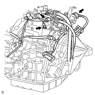
(b) Install the 2 wire harnesses to the automatic transaxle assembly with the 2 bolts.
Torque:
Bolt (A) :
12 N·m {122 kgf·cm, 9 ft·lbf}
Bolt (B) :
8.4 N·m {86 kgf·cm, 74 in·lbf}
12. INSTALL TCM
13. INSTALL MANIFOLD STAY
14. INSTALL STARTER ASSEMBLY
15. INSTALL FRONT CROSSMEMBER SUB-ASSEMBLY
16. INSTALL ENGINE ASSEMBLY WITH TRANSAXLE
HINT:
See the steps from "Install Engine Assembly with Transaxle" through "Inspect
Speed Sensor Signal" (See page ).
17. CHECK AUTOMATIC TRANSAXLE SYSTEM
NOTICE:
If automatic transaxle assembly parts have been replaced, refer to Parts Replacement
Compensation Table to determine if any additional operations are necessary (See
page ).
 Removal
REMOVAL
CAUTION / NOTICE / HINT
NOTICE:
If automatic transaxle assembly parts are replaced, refer to Parts Replacement
Compensation Table to determine if any additional operations are necessary ( ...

Other materials about Toyota Venza:
Installation
INSTALLATION
PROCEDURE
1. INSTALL NO. 2 BACK WINDOW GLASS SPACER
(a) Apply Primer G to the installation part of the No. 2 back window glass spacer.
HINT:
If primer is applied to an area that is not specified, wipe off the primer with
a non-residue solve ...
Problem Symptoms Table
PROBLEM SYMPTOMS TABLE
HINT:
Use the table below to help determine the cause of problem symptoms.
If multiple suspected areas are listed, the potential causes of the symptoms
are listed in order of probability in the "Suspected Area" ...
Data Signal Circuit between Navigation Receiver Assembly and Extension Module
DESCRIPTION
The stereo component tuner assembly sends the image data signal to the navigation
receiver assembly via this circuit.
WIRING DIAGRAM
PROCEDURE
1.
CHECK NAVIGATION WIRE
(a) Remove the navigation wire (See pag ...

0.129