Toyota Venza: Removal
REMOVAL
PROCEDURE
1. DRAIN DIFFERENTIAL OIL
|
(a) Using a 10 mm hexagon wrench, remove the rear differential carrier cover plug and gasket. |
|
.png)
|
(b) Using a 10 mm hexagon wrench, remove the rear differential drain plug and gasket to drain the differential oil. |
|
.png)
2. REMOVE REAR WHEELS
3. REMOVE CENTER EXHAUST PIPE ASSEMBLY
(a) Remove the center exhaust pipe assembly.
HINT:
Refer to the instructions for Removal of the exhaust pipe (See page
.gif) for 2GR-FE,
for 2GR-FE,
for 1AR-FE).
4. REMOVE PROPELLER WITH CENTER BEARING SHAFT ASSEMBLY
5. SEPARATE REAR SPEED SENSOR LH
6. SEPARATE REAR SPEED SENSOR RH
7. REMOVE REAR AXLE SHAFT NUT LH
8. REMOVE REAR AXLE SHAFT NUT RH
9. SEPARATE NO. 3 PARKING BRAKE CABLE ASSEMBLY
10. SEPARATE NO. 2 PARKING BRAKE CABLE ASSEMBLY
11. REMOVE NO. 1 FLOOR UNDER COVER
12. REMOVE REAR STRUT ROD ASSEMBLY LH
13. REMOVE REAR STRUT ROD ASSEMBLY RH
14. REMOVE REAR HEIGHT CONTROL SENSOR SUB-ASSEMBLY (w/ HID Headlight System)
15. REMOVE REAR NO. 2 SUSPENSION ARM ASSEMBLY LH
16. REMOVE REAR NO. 2 SUSPENSION ARM ASSEMBLY RH
17. SEPARATE REAR NO. 1 SUSPENSION ARM ASSEMBLY LH
18. SEPARATE REAR NO. 1 SUSPENSION ARM ASSEMBLY RH
19. REMOVE REAR DRIVE SHAFT ASSEMBLY LH
20. REMOVE REAR DRIVE SHAFT SNAP RING LH
21. REMOVE REAR DRIVE SHAFT ASSEMBLY RH
22. REMOVE REAR DRIVE SHAFT SNAP RING RH
23. SEPARATE NO. 3 FLOOR WIRE (w/ HID Headlight System)
24. SEPARATE FRAME WIRE
25. REMOVE REAR SUSPENSION MEMBER
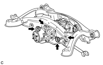
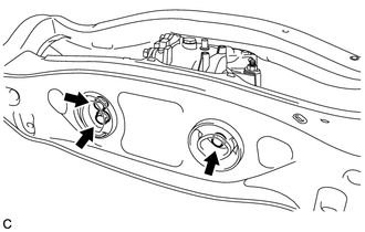
26. REMOVE REAR DIFFERENTIAL CARRIER ASSEMBLY WITH DIFFERENTIAL SUPPORT
|
(a) Remove the 2 bolts and 2 nuts. HINT: The nuts have tabs to prevent them from rotating. |
|
|
(b) Remove the 3 rear mounting bolts and rear differential carrier assembly with differential support from the rear suspension member assembly. |
|
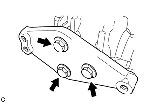
27. REMOVE DIFFERENTIAL SUPPORT
|
(a) Remove the 3 bolts and differential support. |
|
28. REMOVE REAR NO. 1 DIFFERENTIAL SUPPORT
|
(a) Remove the 2 bolts, 2 nuts and rear No. 1 differential support. HINT: The nuts have tabs to prevent them from rotating. |
|
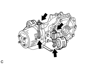
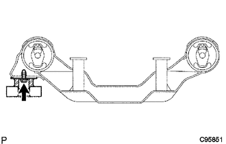
29. REMOVE REAR DIFFERENTIAL DYNAMIC DAMPER
HINT:
This step should be performed only when the rear differential dynamic damper is being replaced.
|
(a) Remove the bolt and rear differential dynamic damper. |
|
 Components
COMPONENTS
ILLUSTRATION
ILLUSTRATION
ILLUSTRATION
ILLUSTRATION
ILLUSTRATION
ILLUSTRATION
ILLUSTRATION
ILLUSTRATION
ILLUSTRATION
...
 Disassembly
DISASSEMBLY
CAUTION / NOTICE / HINT
HINT:
Use an overhaul stand as necessary.
PROCEDURE
1. REMOVE REAR DIFFERENTIAL FILLER PLUG
(a) Remove the rear differential filler plug and gasket ...
Other materials about Toyota Venza:
Installation
INSTALLATION
PROCEDURE
1. INSTALL REAR NO. 1 SUSPENSION ARM ASSEMBLY LH
(a) Temporarily install the rear No. 1 suspension arm assembly LH to
the rear suspension member with the bolt and the nut.
Text in Illustration
*1
...
Camshaft Position Sensor "B" Circuit (Bank 1) (P0365,P0367,P0368)
DESCRIPTION
The camshaft position sensor (EV signal sensor) for the exhaust camshaft consists
of a magnet and MRE (Magneto Resistance Element).
The exhaust camshaft has a timing rotor for the camshaft position sensor. When
the camshaft rotates, changes o ...
How To Proceed With Troubleshooting
CAUTION / NOTICE / HINT
HINT:
Use the following procedure to troubleshoot the key reminder warning
system.
*: Use the Techstream.
PROCEDURE
1.
VEHICLE BROUGHT TO WORKSHOP
NEXT
...

0.1549