Toyota Venza: Installation
INSTALLATION
PROCEDURE
1. INSTALL FUEL PRESSURE PULSATION DAMPER ASSEMBLY
|
(a) Apply a light coat of gasoline or spindle oil to a new O-ring. Text in Illustration
|
|
(b) Install the O-ring to the fuel pressure pulsation damper assembly.
(c) Install the fuel pressure pulsation damper assembly with the 2 bolts.
Torque:
10 N·m {102 kgf·cm, 7 ft·lbf}
NOTICE:
Make sure that the O-ring is not cracked or jammed when installing the damper.
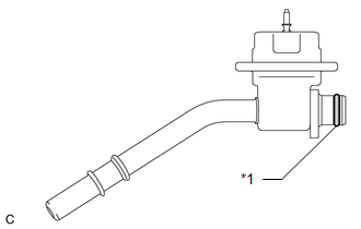
2. INSTALL FUEL TUBE SUB-ASSEMBLY
 Text in Illustration
|
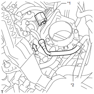
*1 |
No. 2 Fuel Pipe Clamp |
|
*2 |
Fuel Hose Clamp |
.png) |
Push |
(a) Connect the fuel tube.
(b) Push the fuel tube connector until it makes a "click" sound.
(c) Install a new No. 2 fuel pipe clamp.
(d) Push the tube connector into the pipe until the tube connector makes a "click" sound.
.png) Text in Illustration
Text in Illustration
|
*1 |
Fuel Pipe |
|
*2 |
Fuel Tube Connector |
|
*3 |
Nylon Tube |
|
*4 |
O-ring |
|
*5 |
Retainer |
.png) |
Push |
NOTICE:
- Before connecting the connector and fuel pipe, check that there is no damage or foreign matter on the connecting part of the fuel pipe.
- After connecting the fuel tube connector and fuel pipe, check that they are securely connected by trying to pull them apart.
(e) Install the No. 1 fuel pipe clamp.
(f) Install the fuel tube sub-assembly to the fuel hose clamp.
3. INSTALL AIR CLEANER CAP SUB-ASSEMBLY
.gif)
4. INSTALL NO. 1 VACUUM SWITCHING VALVE ASSEMBLY
5. INSTALL NO. 1 ENGINE COVER SUB-ASSEMBLY
6. INSTALL OUTER COWL TOP PANEL
7. INSTALL WINDSHIELD WIPER MOTOR AND LINK ASSEMBLY
(a) Install the windshield wiper motor and link assembly (See page
).
8. CONNECT CABLE TO NEGATIVE BATTERY TERMINAL
NOTICE:
When disconnecting the cable, some systems need to be initialized after the cable
is reconnected (See page ).
9. INSPECT FOR FUEL LEAK
 Removal
REMOVAL
PROCEDURE
1. DISCHARGE FUEL SYSTEM PRESSURE
HINT:
See page
2. DISCONNECT CABLE FROM NEGATIVE BATTERY TERMINAL
NOTICE:
When disconnecting the cable, some systems need to be initialized ...

Other materials about Toyota Venza:
Air Mix Damper Control Servo Motor Circuit (Driver Side) (B1446/46)
DESCRIPTION
The air mix control servo motor sends pulse signals to indicate the damper position
to the A/C amplifier. The A/C amplifier activates the motor (normal or reverse)
based on these signals to move the air mix damper (driver side) to any position ...
Camshaft Position "B" Actuator Circuit / Open (Bank 1) (P0013)
DESCRIPTION
The Variable Valve Timing (VVT) system adjusts the exhaust valve timing to improve
driveability. The engine oil pressure turns the VVT controller to adjust the valve
timing.
The camshaft timing oil control valve is a solenoid valve and switch ...
Coolant Thermostat (Coolant Temperature Below Thermostat Regulating Temperature)
(P0128)
DESCRIPTION
HINT:
This DTC relates to the thermostat.
This DTC is stored when the engine coolant temperature does not reach 75°C (167°F)
despite sufficient engine warm-up time having elapsed.
DTC No.
DTC Detection Condition
...

0.113