Toyota Venza: Removal
REMOVAL
PROCEDURE
1. DISCONNECT CABLE FROM NEGATIVE BATTERY TERMINAL
NOTICE:
When disconnecting the cable, some systems need to be initialized after the cable
is reconnected (See page .gif) ).
).
2. REMOVE FRONT WHEEL RH
3. REMOVE NO. 1 ENGINE UNDER COVER
4. SEPARATE FRONT FENDER LINER RH
5. REMOVE FRONT FENDER APRON SEAL RH
6. REMOVE COOL AIR INTAKE DUCT SEAL
7. REMOVE NO. 1 ENGINE COVER SUB-ASSEMBLY
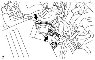
8. REMOVE INLET AIR CLEANER ASSEMBLY
9. REMOVE AIR CLEANER CAP SUB-ASSEMBLY
|
(a) Disconnect the mass air flow meter connector and separate the wire harness clamp from the air cleaner cap. |
|
(b) Loosen the hose clamp and disconnect the air cleaner hose.
|
(c) Remove the 2 bolts and air cleaner cap sub-assembly. |
|
.png)
10. REMOVE AIR CLEANER FILTER ELEMENT SUB-ASSEMBLY
11. REMOVE AIR CLEANER CASE SUB-ASSEMBLY
12. REMOVE NO. 2 ENGINE MOUNTING STAY RH
13. REMOVE ENGINE MOVING CONTROL ROD
14. DISCONNECT VENTILATION HOSE ASSEMBLY
|
(a) Disconnect the ventilation hose from the cylinder head cover. |
|
.png)
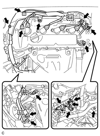
15. DISCONNECT ENGINE WIRE
|
(a) Disconnect the connectors and clamps, remove the bolts and nuts and disconnect the engine wire from the engine. |
|
16. REMOVE IGNITION COIL ASSEMBLY
17. REMOVE CYLINDER HEAD COVER SUB-ASSEMBLY
18. SET NO. 1 CYLINDER TO TDC/COMPRESSION
|
(a) Turn the crankshaft pulley until its timing notch (groove) and the timing mark "0" of the timing chain cover are aligned. Text in Illustration
|
|
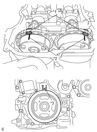
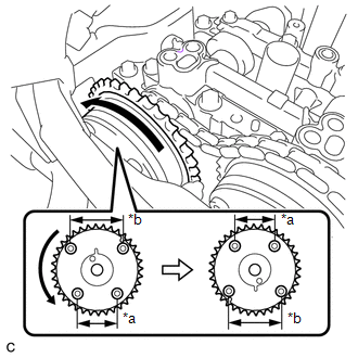
(b) Check that each matchmark of the camshaft timing gear and camshaft timing exhaust gear are aligned with each matchmark located as shown in the illustration. If not, turn the crankshaft 1 revolution (360°) to align the timing marks as shown in the illustration.
(c) Place paint marks on the chain in alignment with the timing marks on the camshaft timing gear and camshaft timing exhaust gear.
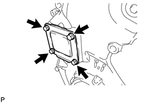
19. REMOVE TIMING CHAIN COVER PLATE
|
(a) Remove the 4 bolts, timing chain cover plate and gasket. |
|
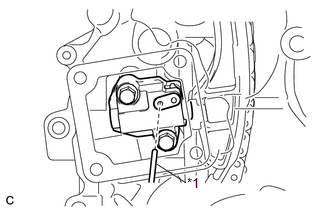
20. REMOVE NO. 1 CHAIN TENSIONER ASSEMBLY
|
(a) Turn the crankshaft approximately 10° clockwise. |
|
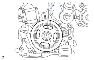
|
(b) Turn the crankshaft approximately 10° counterclockwise. |
|
|
(c) Align the holes of the stopper plate and tensioner, and insert a pin into the stopper plate hole to lock the tensioner. Text in Illustration
|
|
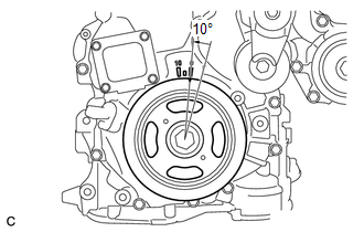
|
(d) Turn the crankshaft approximately 10° clockwise. |
|
|
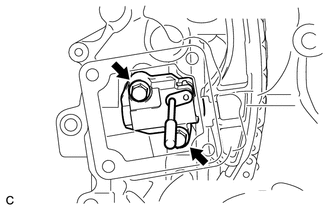
(e) Remove the 2 bolts, chain tensioner and gasket. NOTICE: Make sure not to drop the gasket inside the timing chain cover. |
|
|
(f) Turn the crankshaft approximately 10° counterclockwise. |
|
21. REMOVE TIMING CHAIN GUIDE
22. REMOVE TIMING CHAIN COVER TIGHT PLUG
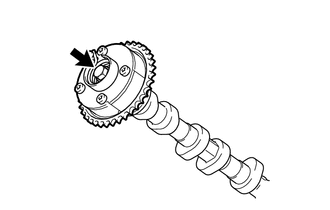
23. REMOVE CAMSHAFT TIMING GEAR ASSEMBLY
|
(a) Hold the hexagonal portion of the camshaft with a wrench and remove the bolt from the camshaft. NOTICE: Be careful not to damage the cylinder head or spark plug tube with the wrench. |
|
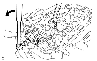
|
(b) Separate the camshaft timing gear assembly from the camshaft. |
|
|
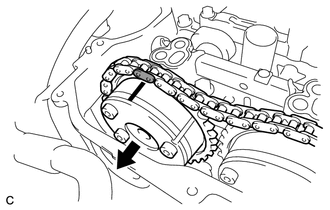
(c) Remove the timing chain from the camshaft timing gear assembly, and turn the camshaft timing gear assembly approximately 180°. Text in Illustration
|
|
|
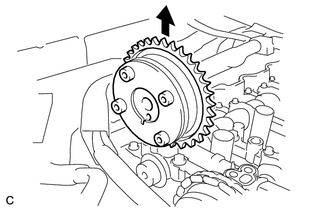
(d) Remove the camshaft timing gear assembly. NOTICE: Do not disassemble the camshaft timing gear. |
|
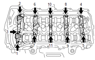
24. REMOVE CAMSHAFT BEARING CAP
|
(a) Using several steps, remove the 11 bearing cap bolts in the sequence shown in the illustration. |
|
|
(b) Using several steps, remove the 10 bearing cap bolts in the sequence shown in the illustration. |
|
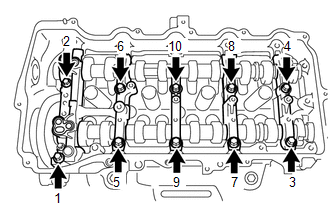
(c) Remove the 5 bearing caps.
HINT:
Arrange the removed parts in the correct order.
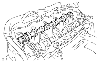
25. REMOVE CAMSHAFT
|
(a) Remove the camshaft from the camshaft housing. |
|
26. REMOVE NO. 2 CAMSHAFT
|
(a) Hold up the chain and remove the No. 2 camshaft from the camshaft housing. |
|
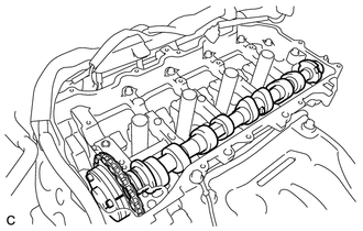
|
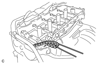
(b) Suspend the chain with a string or equivalent as shown in the illustration. NOTICE: Be careful not to drop the chain inside the timing chain cover. |
|
27. REMOVE CAMSHAFT TIMING EXHAUST GEAR ASSEMBLY
|
(a) Remove the flange bolt and camshaft timing exhaust gear assembly. NOTICE: Do not disassemble the camshaft timing exhaust gear. |
|
28. REMOVE OIL CONTROL VALVE FILTER
29. REMOVE NO. 1 CAMSHAFT BEARING
30. REMOVE NO. 2 CAMSHAFT BEARING
 Components
COMPONENTS
ILLUSTRATION
ILLUSTRATION
...
 Installation
INSTALLATION
CAUTION / NOTICE / HINT
HINT:
Perform "Inspection After Repair" after replacing the camshaft, No. 2 camshaft,
camshaft timing gear assembly or camshaft timing exhaust gear ...
Other materials about Toyota Venza:
Adjustment
ADJUSTMENT
CAUTION / NOTICE / HINT
CAUTION:
Before adjusting the door positions of vehicles equipped with side and curtain
shield airbags, be sure to disconnect the battery. After adjustment, check that
the SRS warning light is operating normally and ...
Illumination for Panel Switch does not Come on with Tail Switch ON
PROCEDURE
1.
CHECK VEHICLE SIGNAL (OPERATION CHECK)
(a) Enter the "Vehicle Signal Check Mode" screen. Refer to Check Vehicle Signal
in Operation Check (See page ).
(b) Check that the display changes between ON ...
System Description
SYSTEM DESCRIPTION
1. ACCESSORY METER ASSEMBLY
(a) Warning or Indicator
Item
Detail
Front passenger side seat belt warning light
Receives a front passenger side seat belt warning light signal from the
co ...

0.1495