Toyota Venza: Components
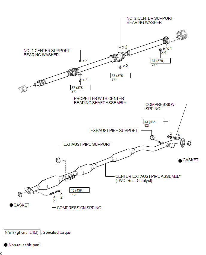
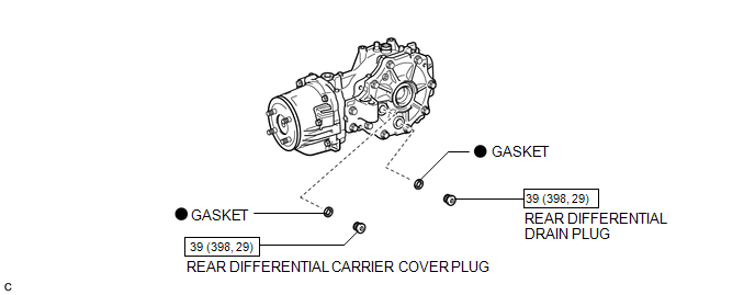
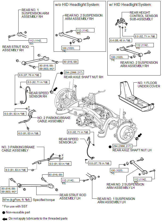
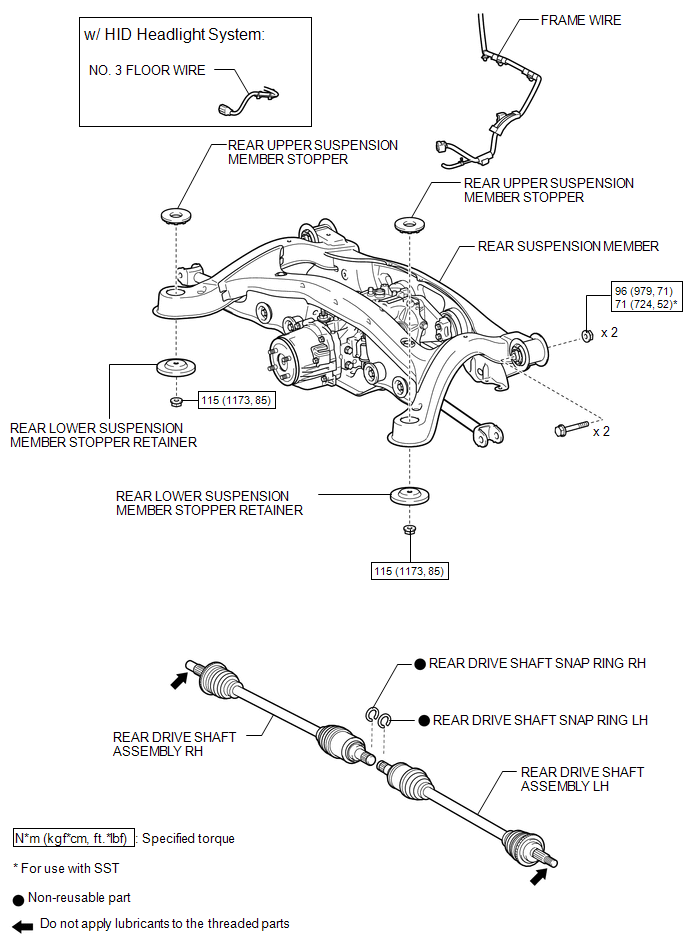
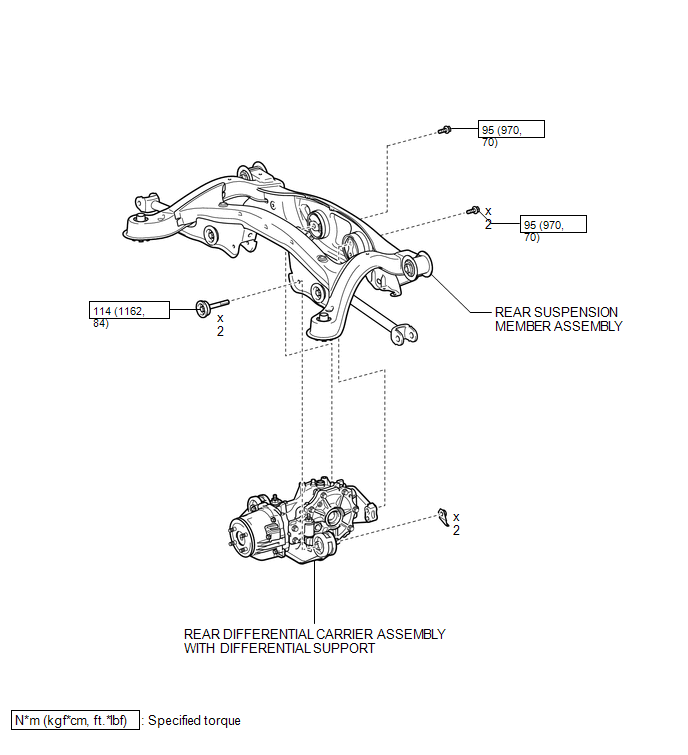
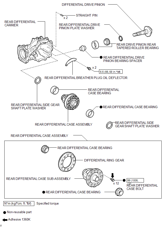
COMPONENTS
ILLUSTRATION
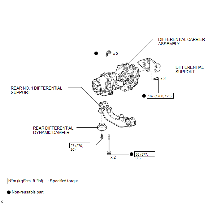
ILLUSTRATION
ILLUSTRATION
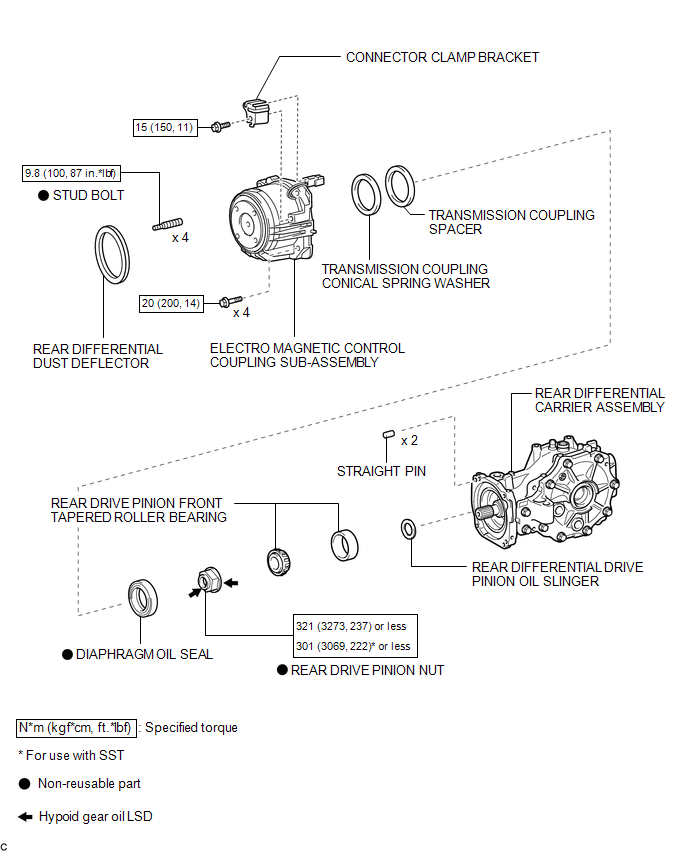
ILLUSTRATION
ILLUSTRATION
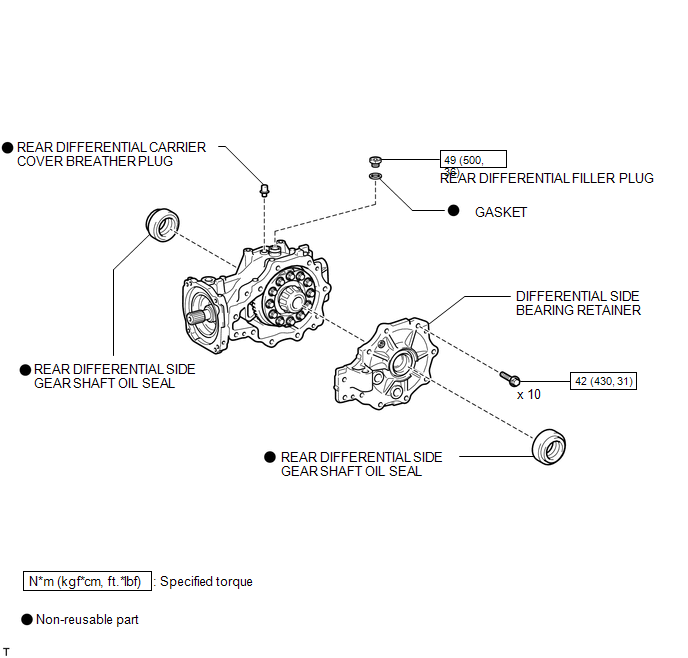
ILLUSTRATION
ILLUSTRATION
ILLUSTRATION
ILLUSTRATION

 Removal
REMOVAL
PROCEDURE
1. DRAIN DIFFERENTIAL OIL
(a) Using a 10 mm hexagon wrench, remove the rear differential carrier
cover plug and gasket.
...
Other materials about Toyota Venza:
Radio Antenna
Components
COMPONENTS
ILLUSTRATION
ILLUSTRATION
Installation
INSTALLATION
PROCEDURE
1. INSTALL RADIO ANTENNA ASSEMBLY
(a) Engage the 2 claws to install the radio antenna assembly.
(b) Place the antenna cord in the cutout of the ante ...
Diagnosis Circuit
DESCRIPTION
The headlight leveling ECU assembly outputs DTC information to the Techstream
via this circuit.
WIRING DIAGRAM
PROCEDURE
1.
CHECK HARNESS AND CONNECTOR (DLC3 - HEADLIGHT LEVELING ECU ASSEMBLY)
(a) Disconnect ...
On-vehicle Inspection
ON-VEHICLE INSPECTION
PROCEDURE
1. INSPECT BRAKE BOOSTER ASSEMBLY
(a) Airtightness check
(1) Start the engine and stop it after 1 or 2 minutes. Slowly depress
the brake pedal several times.
HINT:
If the pedal can be depressed to the ...

0.1565