Toyota Venza: Removal
REMOVAL
PROCEDURE
1. REMOVE REAR BUMPER ASSEMBLY
(See page .gif) )
)
2. REMOVE ULTRASONIC SENSOR CLIP
|
(a) Disconnect the connector. Text in Illustration
|
|
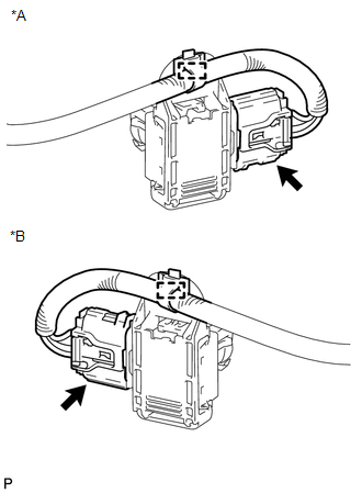
(b) Disengage the clamp.
|
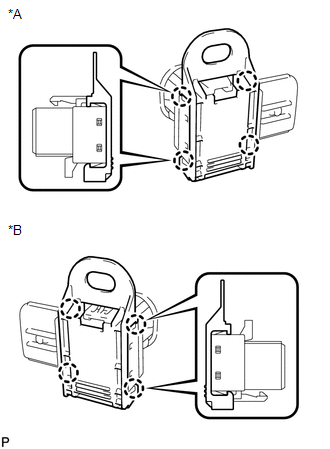
(c) Disengage the 4 claws to remove the ultrasonic sensor clip. Text in Illustration
|
|
3. REMOVE NO. 1 ULTRASONIC SENSOR
|
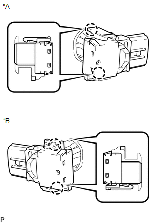
(a) Disengage the 2 claws to remove the No. 1 ultrasonic sensor. Text in Illustration
|
|
4. REMOVE NO. 1 ULTRASONIC SENSOR RETAINER
|
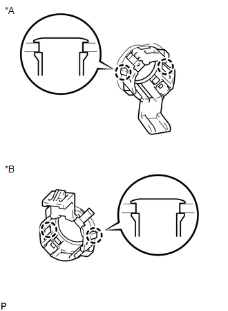
(a) Disengage the 2 claws to remove the No. 1 ultrasonic sensor retainer from the rear bumper assembly. Text in Illustration
|
|
 Inspection
INSPECTION
PROCEDURE
1. INSPECT NO. 1 ULTRASONIC SENSOR
(a) Measure the resistance according to the value(s) in the table below.
Standard Resistance:
Tester Conne ...
 Installation
INSTALLATION
PROCEDURE
1. INSTALL NO. 1 ULTRASONIC SENSOR RETAINER
(a) Engage the 2 claws to install the No. 1 ultrasonic sensor retainer
to the rear bumper assembly.
Text in Illu ...
Other materials about Toyota Venza:
Relay
On-vehicle Inspection
ON-VEHICLE INSPECTION
PROCEDURE
1. INSPECT RR DEF RELAY
(a) Measure the resistance according to the value(s) in the table below.
Standard Resistance:
Tester Connection
Condition
...
Freeze Frame Data
FREEZE FRAME DATA
1. FREEZE FRAME DATA
(a) Whenever a DTC is detected, the AFS ECU (headlight swivel ECU assembly) stores
the current vehicle (sensor) state as Freeze Frame Data.
2. CHECK FREEZE FRAME DATA
(a) Connect the Techstream to the DLC3.
(b) Tur ...
Malfunction in Deceleration Sensor (C0365/28,C1234/34,C1245/32,C1245/45)
DESCRIPTION
The skid control ECU receives signals from the yaw rate and acceleration sensor
via the CAN communication system.
The yaw rate sensor has a built-in acceleration sensor.
If there is trouble in the bus lines between the yaw rate and acceleratio ...

0.1325