Toyota Venza: Installation
INSTALLATION
PROCEDURE
1. INSTALL FRONT SHOULDER BELT ANCHOR ADJUSTER ASSEMBLY
|
(a) Engage the adjuster positioning hole with the guide and install the front shoulder belt anchor adjuster assembly with the 2 bolts. Torque: 42 N·m {428 kgf·cm, 31 ft·lbf} |
|
.png)
2. INSTALL FRONT SEAT OUTER BELT ASSEMBLY
|
(a) Engage the 2 guides. |
|
.png)
(b) Install the front seat outer belt assembly with the bolt.
Torque:
7.5 N·m {77 kgf·cm, 66 in·lbf}
|
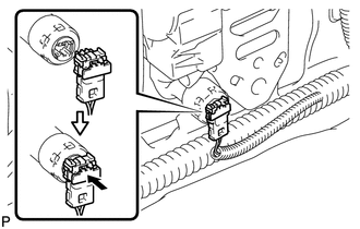
(c) Connect the connector and lock the locking button as shown in the illustration. NOTICE: Securely lock the locking button. |
|
|
(d) Connect the shoulder anchor of the front seat outer belt assembly with the nut. Torque: 42 N·m {428 kgf·cm, 31 ft·lbf} |
|
.png)
3. INSTALL UPPER CENTER PILLAR GARNISH
.gif)
4. INSTALL LOWER CENTER PILLAR GARNISH
5. CONNECT FRONT SEAT OUTER BELT ASSEMBLY
|
(a) Install the floor end of the front seat outer belt assembly with the bolt. Torque: 42 N·m {428 kgf·cm, 31 ft·lbf} |
|
.png)
(b) Check if the ELR locks.
NOTICE:
The check should be performed with the outer belt assembly installed.
(1) With the belt assembly installed, check that the belt locks when it is pulled out quickly.
6. INSTALL LAP BELT OUTER ANCHOR COVER
|
(a) Engage the 3 claws to install the lap belt outer anchor cover. |
|
.png)
7. CONNECT REAR DOOR OPENING TRIM WEATHERSTRIP
|
(a) Connect the rear door opening trim weatherstrip. |
|
.png)
8. INSTALL REAR DOOR SCUFF PLATE
9. CONNECT FRONT DOOR OPENING TRIM WEATHERSTRIP
|
(a) Connect the front door opening trim weatherstrip. |
|
.png)
10. INSTALL FRONT DOOR SCUFF PLATE
11. CONNECT CABLE TO NEGATIVE BATTERY TERMINAL
NOTICE:
When disconnecting the cable, some systems need to be initialized after the cable
is reconnected (See page ).
12. INSPECT SRS WARNING LIGHT
(a) Inspect the SRS warning light (See page
).
 Inspection
INSPECTION
PROCEDURE
1. INSPECT FRONT SEAT OUTER BELT ASSEMBLY
NOTICE:
Do not disassemble the retractor.
(a) Before installing the front seat outer belt assembly, check the ELR.
(1) When the i ...
 Disposal
DISPOSAL
CAUTION / NOTICE / HINT
CAUTION:
Before performing pre-disposal deployment of any SRS component, review and closely
follow all applicable environmental and hazardous material regulations ...
Other materials about Toyota Venza:
Lost Communication with AFS LIN (B124D)
DESCRIPTION
Refer to DTC B124D (Lighting system) (See page
).
DTC No.
DTC Detection Condition
Trouble Area
B124D
Malfunctions in LIN communication system
Inner rear view mir ...
Data Signal Circuit between Radio Receiver and Stereo Jack Adapter
DESCRIPTION
The No. 1 stereo jack adapter assembly sends the sound data signal or image data
signal from a USB device to the radio and display receiver assembly via this circuit.
WIRING DIAGRAM
PROCEDURE
1.
CHECK HARNESS AND CONN ...
Torque Sensor Zero Point Adjustment Incomplete (C1516,C1526)
DESCRIPTION
These DTCs do not indicate a malfunction. The power steering ECU stores these
DTCs when it determines that the rotation angle sensor value initialization and
torque sensor zero point calibration are incomplete.
DTC No.
D ...

0.1621