Toyota Venza: Disassembly
DISASSEMBLY
PROCEDURE
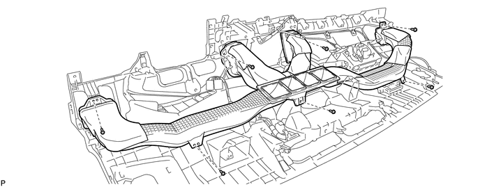
1. REMOVE NO. 1 SIDE DEFROSTER NOZZLE DUCT
|
(a) Remove the 2 screws <E> or <F> and remove the No. 1 side defroster nozzle duct. |
|
2. REMOVE NO. 2 SIDE DEFROSTER NOZZLE DUCT
|
(a) Remove the 2 screws <E> or <F> and remove the No. 2 side defroster nozzle duct. |
|
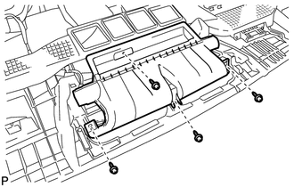
3. REMOVE DEFROSTER NOZZLE ASSEMBLY
|
(a) Remove the 4 screws <E> or <F> and remove the defroster nozzle assembly. |
|
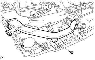
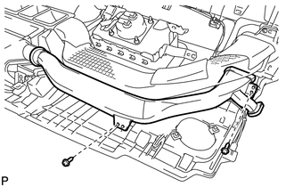
4. REMOVE HEATER TO REGISTER DUCT
(a) Remove the 7 screws <E> or <F> and remove the heater to register duct.
5. REMOVE NO. 1 ANTENNA CORD SUB-ASSEMBLY
.gif)
6. REMOVE NAVIGATION ANTENNA ASSEMBLY (w/ Navigation System)
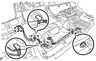
7. REMOVE NO. 3 INSTRUMENT PANEL WIRE
|
(a) Disengage the 4 clamps and remove the No. 3 instrument panel wire. |
|
8. REMOVE FRONT PASSENGER AIRBAG ASSEMBLY
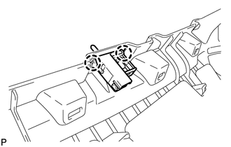
9. REMOVE GLOVE BOX LIGHT ASSEMBLY
|
(a) Disengage the 2 claws and remove the glove box light assembly. |
|
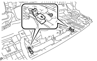
10. REMOVE NO. 1 INSTRUMENT PANEL PIN
|
(a) Remove the 2 screws <E> or <F> and the 2 No. 1 instrument panel pins. |
|
 Removal
REMOVAL
PROCEDURE
1. PRECAUTION
(See page )
2. ALIGN FRONT WHEELS FACING STRAIGHT AHEAD
3. DISCONNECT CABLE FROM NEGATIVE BATTERY TERMINAL
CAUTION:
Wait at least 90 seconds after disconnecting ...
 Reassembly
REASSEMBLY
PROCEDURE
1. INSTALL NO. 1 INSTRUMENT PANEL PIN
(a) Install the 2 No. 1 instrument panel pins with the 2 screws <E> or
<F>.
...
Other materials about Toyota Venza:
Inspection
INSPECTION
PROCEDURE
1. INSPECT LUMBAR SUPPORT ADJUSTER ASSEMBLY
(a) Check operation of the lumbar support adjuster.
(1) Check if the lumbar support adjuster moves smoothly when the battery is connected
to the lumbar support adjuster motor connector te ...
Evaporative Emission Control System Leak Detected (Gross Leak) (P0455,P0456)
DTC SUMMARY
DTC No.
Monitoring Item
Malfunction Detection Condition
Trouble Area
Detection Timing
Detection Logic
P0455
EVAP gross leak
Leak detection pum ...
Removal
REMOVAL
PROCEDURE
1. REMOVE NO. 1 SLIDING ROOF GLASS SUB-ASSEMBLY
(a) Fully open the No. 2 sliding roof glass sub-assembly.
(b) Using a T20 "TORX" socket wrench, remove the 6 screws and No. 1 sliding
roof glass sub-assembly.
...

0.1589