Toyota Venza: Installation
INSTALLATION
PROCEDURE
1. INSTALL NO. 1 ULTRASONIC SENSOR RETAINER
|
(a) Engage the 2 claws to install the No. 1 ultrasonic sensor retainer to the rear bumper assembly. Text in Illustration
NOTICE:
HINT:
|
|
2. INSTALL NO. 1 ULTRASONIC SENSOR
|
(a) Engage the 2 claws to install the No. 1 ultrasonic sensor to the No. 1 ultrasonic sensor retainer. Text in Illustration
NOTICE: Push the No. 1 ultrasonic sensor retainer from the outside of the rear bumper assembly when there is a gap between the No. 1 ultrasonic sensor retainer and the rear bumper assembly surface. In this case, do not push on the No .1 ultrasonic sensor. |
|
.png)
3. INSTALL ULTRASONIC SENSOR CLIP
|
(a) Engage the 4 claws to install the ultrasonic sensor clip. Text in Illustration
|
|
.png)
|
(b) Engage the clamp. Text in Illustration
|
|
.png)
(c) Connect the connector.
4. INSTALL REAR BUMPER ASSEMBLY
(See page .gif) )
)
 Removal
REMOVAL
PROCEDURE
1. REMOVE REAR BUMPER ASSEMBLY
(See page )
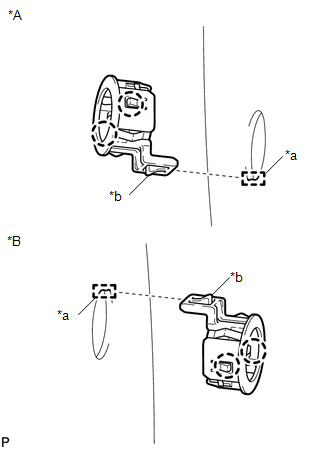
2. REMOVE ULTRASONIC SENSOR CLIP
(a) Disconnect the connector.
Text in Illustration
*A
...
 Brake (front)
...
Other materials about Toyota Venza:
Definition Of Terms
DEFINITION OF TERMS
Term
Definition
Monitor Description
Description of what the ECM monitors and how it detects malfunctions
(monitoring purpose and details).
Related DTCs
Group ...
Engine Coolant Temperature Circuit Range / Performance Problem (P0116)
DESCRIPTION
Refer to DTC P0115 (See page ).
DTC No.
DTC Detection Condition
Trouble Area
P0116
When either of the following conditions is met (2 trip detection logic).
During engine ...
Open in Front Floor Electrical Key Oscillator Circuit (B27A5)
DESCRIPTION
The certification ECU (smart key ECU assembly) generates a request signal and
sends it to the indoor electrical key oscillator (for front floor). To detect the
key inside the cabin, the indoor electrical key oscillator (for front floor) create ...

0.1215