
Toyota Venza: Reassembly
REASSEMBLY
PROCEDURE
1. INSTALL COOLER DRYER
|
(a) Using pliers, install a new cooler dryer to the modulator. |
|
.png)
|
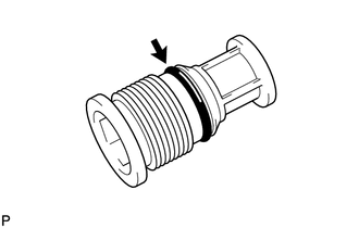
(b) Apply sufficient compressor oil to the O-ring and fitting surfaces of the cap. Compressor oil: ND-OIL 8 or equivalent |
|
|
(c) Using a 14 mm straight hexagon wrench, install the cap to the cooler condenser core. NOTICE: Keep the O-rings and O-ring fitting surfaces clean from dirt or any foreign objects. Torque: 2.9 N·m {30 kgf·cm, 26 in·lbf} Text in Illustration
|
|
.png)
 Installation
INSTALLATION
PROCEDURE
1. INSTALL COOLER CONDENSER ASSEMBLY
(a) Install the cooler condenser assembly with the 4 bolts.
Torque:
6.0 N·m {61 kgf·cm, 53 in·lbf}
HINT:
If th ...
 Front Blower Motor
Components
COMPONENTS
ILLUSTRATION
Installation
INSTALLATION
PROCEDURE
1. INSTALL FRONT BLOWER MOTOR SUB-ASSEMBLY
(a) Install the front blower motor sub-assembly with the 3 scr ...
Other materials about Toyota Venza:
Installation
INSTALLATION
CAUTION / NOTICE / HINT
HINT:
Use the same procedure for the RH side and LH side.
The following procedure is for the LH side.
The rear speed sensor is a component of the rear axle hub and bearing
assembly. If the sensor malf ...
System Description
SYSTEM DESCRIPTION
1. FRONT POWER SEAT CONTROL SYSTEM DESCRIPTION
The driver seat is equipped with slide, reclining, lifter, front vertical,
and lumbar support adjustment functions.
The memory call function uses the key ID code of the key to m ...
Installation
INSTALLATION
PROCEDURE
1. INSTALL STUD BOLT (for LH Side)
(a) Using SST and a socket wrench (21 mm), install the stud bolt.
Text in Illustration
*1
Socket Wrench
*2
...

0.193