Toyota Venza: Removal
REMOVAL
PROCEDURE
1. DISCONNECT CABLE FROM NEGATIVE BATTERY TERMINAL
CAUTION:
Wait at least 90 seconds after disconnecting the cable from the negative (-)
battery terminal to disable the SRS system (See page
.gif) ).
).
NOTICE:
When disconnecting the cable, some systems need to be initialized after the cable
is reconnected (See page ).
2. REMOVE REAR DOOR INSIDE HANDLE BEZEL PLUG
3. REMOVE REAR POWER WINDOW REGULATOR SWITCH ASSEMBLY WITH REAR DOOR ARMREST BASE PANEL
4. REMOVE REAR DOOR TRIM BOARD SUB-ASSEMBLY
5. REMOVE REAR DOOR INNER GLASS WEATHERSTRIP
6. REMOVE REAR SPEAKER ASSEMBLY
|
(a) Disconnect the connector. |
|
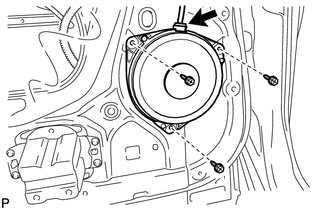
(b) Remove the 3 bolts and rear speaker assembly.
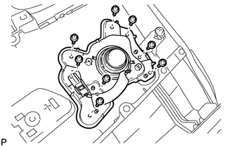
7. REMOVE REAR SPEAKER BRACKET (for 13 Speakers)
|
(a) Remove the 8 screws, rear speaker bracket and rear door speaker grille sub-assembly. |
|
8. REMOVE REAR NO. 2 SPEAKER ASSEMBLY (for 13 Speakers)
|
(a) Remove the 2 screws. |
|
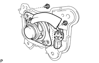
(b) Disengage the clamp and remove the rear No. 2 speaker assembly.
 Components
COMPONENTS
ILLUSTRATION
...
 Inspection
INSPECTION
PROCEDURE
1. INSPECT REAR SPEAKER ASSEMBLY
(a) With the speaker installed, check that there is no looseness or other abnormalities.
(b) Check that there is no foreign matter in the spea ...
Other materials about Toyota Venza:
Components
COMPONENTS
ILLUSTRATION
ILLUSTRATION
ILLUSTRATION
ILLUSTRATION
ILLUSTRATION
ILLUSTRATION
ILLUSTRATION
ILLUSTRATION
...
Receiver Error (C2176/76)
DESCRIPTION
The signals are transmitted to the tire pressure warning antenna and receiver
on the body as radio waves and then sent to the tire pressure warning ECU.
DTC No.
DTC Detection Condition
Trouble Area
...
IG Power Source Circuit
DESCRIPTION
The main power source is supplied to the A/C amplifier when the ignition switch
is ON.
The power source is used for operating the A/C amplifier and servo motor, etc.
WIRING DIAGRAM
CAUTION / NOTICE / HINT
NOTICE:
Inspect the fuses for cir ...

0.1511