Toyota Venza: Components
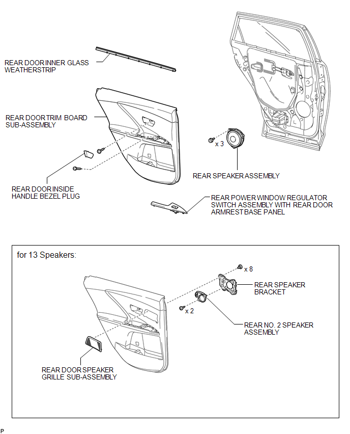
COMPONENTS
ILLUSTRATION

 Removal
REMOVAL
PROCEDURE
1. DISCONNECT CABLE FROM NEGATIVE BATTERY TERMINAL
CAUTION:
Wait at least 90 seconds after disconnecting the cable from the negative (-)
battery terminal to disable the SRS sys ...
Other materials about Toyota Venza:
Mass or Volume Air Flow Circuit Low Input (P0102,P0103)
DESCRIPTION
The mass air flow meter is a sensor that measures the amount of air flowing through
the throttle valve. The ECM uses this information to determine the fuel injection
time and to provide the appropriate air-fuel ratio.
Inside the mass air flow ...
System Diagram
SYSTEM DIAGRAM
Transmitting ECU
(Transmitter)
Receiving ECU
Signal
Communication Method
Center Airbag Sensor Assembly
ECM
Crash detection signal
CAN
...
Components
COMPONENTS
ILLUSTRATION
ILLUSTRATION
ILLUSTRATION
ILLUSTRATION
ILLUSTRATION
ILLUSTRATION
ILLUSTRATION
ILLUSTRATION
...

0.1412