Toyota Venza: Back-up Power Source Circuit
DESCRIPTION
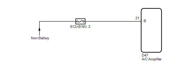
The back-up power source circuit for the A/C amplifier is shown below. Power is supplied even when the ignition switch is turned off. The power is used for diagnostic trouble code memory, etc.
WIRING DIAGRAM
CAUTION / NOTICE / HINT
NOTICE:
Inspect the fuses for circuits related to this system before performing the following inspection procedure.
PROCEDURE
|
1. |
CHECK HARNESS AND CONNECTOR (A/C AMPLIFIER - BATTERY) |
|
(a) Disconnect the A/C amplifier connector. |
|
(b) Measure the voltage according to the value(s) in the table below.
Standard Voltage:
|
Tester Connection |
Condition |
Specified Condition |
|---|---|---|
|
D47-21 (B) - Body ground |
Always |
11 to 14 V |
|
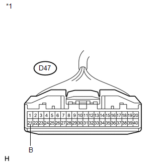
*1 |
Front view of wire harness connector (to A/C Amplifier) |
| OK | .gif) |
PROCEED TO NEXT SUSPECTED AREA SHOWN IN PROBLEM SYMPTOMS TABLE |
| NG | |
REPAIR OR REPLACE HARNESS OR CONNECTOR |
 IG Power Source Circuit
DESCRIPTION
The main power source is supplied to the A/C amplifier when the ignition switch
is ON.
The power source is used for operating the A/C amplifier and servo motor, etc.
WIRING DIAGRAM
...

Other materials about Toyota Venza:
Components
COMPONENTS
ILLUSTRATION
ILLUSTRATION
ILLUSTRATION
ILLUSTRATION
ILLUSTRATION
...
Steering Lock Position Signal Circuit Malfunction (B2285)
DESCRIPTION
This DTC is stored when serial communication signals and LIN communication signals
in the circuit between the power management control ECU and steering lock actuator
assembly (steering lock ECU) are inconsistent.
DTC No.
...
MIL Circuit
DESCRIPTION
The MIL (Malfunction Indicator Lamp) is used to indicate vehicle malfunctions
detected by the ECM. By turning the ignition switch to ON, power is supplied to
the MIL circuit, and the ECM provides the circuit ground which illuminates the MIL.
...

0.2251