Toyota Venza: Inspection
INSPECTION
PROCEDURE
1. INSPECT REAR SPEAKER ASSEMBLY
(a) With the speaker installed, check that there is no looseness or other abnormalities.
(b) Check that there is no foreign matter in the speaker, no tears on the speaker cone or other abnormalities.
|
(c) Measure the resistance of the speaker. Standard Resistance: for 6 Speakers:
If the result is not as specified, replace the speaker. Text in Illustration
|
|
.png)
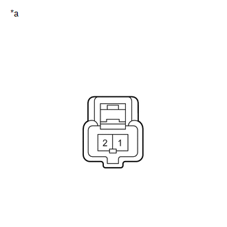
2. INSPECT REAR NO. 2 SPEAKER ASSEMBLY (for 13 Speakers)
(a) With the speaker installed, check that there is no looseness or other abnormalities.
(b) Check that there is no foreign matter in the speaker, no tears on the speaker cone or other abnormalities.
|
(c) Measure the resistance of the speaker. Standard Resistance:
If the result is not as specified, replace the speaker. Text in Illustration
|
|
 Removal
REMOVAL
PROCEDURE
1. DISCONNECT CABLE FROM NEGATIVE BATTERY TERMINAL
CAUTION:
Wait at least 90 seconds after disconnecting the cable from the negative (-)
battery terminal to disable the SRS sys ...
 Installation
INSTALLATION
PROCEDURE
1. INSTALL REAR NO. 2 SPEAKER ASSEMBLY (for 13 Speakers)
(a) Install the rear No. 2 speaker assembly with the 2 screws.
...
Other materials about Toyota Venza:
On-vehicle Inspection
ON-VEHICLE INSPECTION
PROCEDURE
1. INSPECT COMPRESSOR FOR METALLIC SOUND
(a) Check if there is abnormal metallic sound from the A/C compressor (compressor
with pulley) when the A/C switch is on and the A/C compressor (compressor with pulley)
operates.
...
Random / Multiple Cylinder Misfire Detected (P0300-P0304)
DESCRIPTION
When the engine misfires, high concentrations of hydrocarbons (HC) enter the
exhaust gas. Extremely high hydrocarbon concentration levels can cause an increase
in exhaust emission levels. Extremely high concentrations of hydrocarbons can also ...
Removal
REMOVAL
PROCEDURE
1. REMOVE ENGINE ASSEMBLY WITH TRANSAXLE
(a) Remove the engine and transaxle (See page
).
2. REMOVE EXHAUST MANIFOLD CONVERTER SUB-ASSEMBLY
(a) Remove the exhaust manifold converter (See page
).
3. REMOVE THROTTLE BODY ASSEMBLY
...

0.1304