Toyota Venza: Removal
REMOVAL
CAUTION / NOTICE / HINT
HINT:
- Use the same procedure for the RH side and LH side.
- The procedure listed below is for the LH side.
PROCEDURE
1. PRECAUTION
CAUTION:
Be sure to read Precaution thoroughly before servicing (See page
.gif) ).
).
2. DISCONNECT CABLE FROM NEGATIVE BATTERY TERMINAL
CAUTION:
Wait at least 90 seconds after disconnecting the cable from the negative (-) battery terminal to disable the SRS system.
NOTICE:
When disconnecting the cable, some systems need to be initialized after the cable
is reconnected (See page ).
3. REMOVE COOL AIR INTAKE DUCT SEAL
4. REMOVE RADIATOR GRILLE
5. REMOVE FRONT AIRBAG SENSOR
|
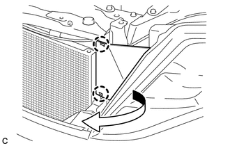
(a) Disengage the 2 claws to separate the radiator side deflector LH as shown in the illustration. |
|
(b) Check that the ignition switch is off.
(c) Check that the cable is disconnected from the negative (-) battery terminal.
CAUTION:
Wait at least 90 seconds after disconnecting the cable from the negative (-) battery terminal to disable the SRS system.
(d) Disconnect the connector from the front airbag sensor.
NOTICE:
When disconnecting the airbag connector, take care not to damage the airbag wire harness.
(1) Push down the white housing lock and slide the yellow CPA. (At this time, the connector cannot be disconnected yet.)
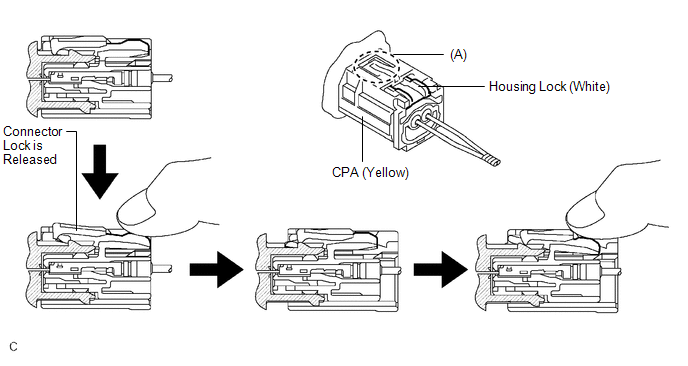
(2) Push down the white housing lock again and disconnect the connector.
NOTICE:
Do not push down part (A) shown in the illustration when disconnecting.
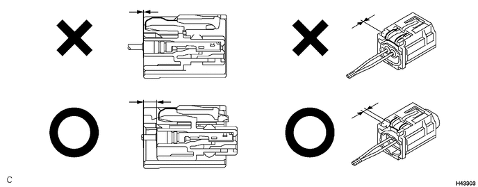
(3) After disconnecting the connector, check that the position of the white housing lock is correct as shown in the illustration.
|
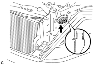
(e) Remove the bolt and front airbag sensor from the body. NOTICE: Loosen the bolt while holding the front airbag sensor because the front airbag sensor pin (stopper) is easily damaged. |
|
 On-vehicle Inspection
ON-VEHICLE INSPECTION
CAUTION / NOTICE / HINT
CAUTION:
Be sure to follow the correct removal and installation procedures of the front
airbag sensor.
PROCEDURE
1. INSPECT FRONT AIRBAG SENSOR (VE ...
 Installation
INSTALLATION
CAUTION / NOTICE / HINT
HINT:
Use the same procedure for the RH side and LH side.
The procedure listed below is for the LH side.
PROCEDURE
1. INSTALL FRONT AIRBAG S ...
Other materials about Toyota Venza:
On-vehicle Inspection
ON-VEHICLE INSPECTION
CAUTION / NOTICE / HINT
CAUTION:
Be sure to follow the correct removal and installation procedures of the curtain
shield airbag assembly.
PROCEDURE
1. INSPECT CURTAIN SHIELD AIRBAG ASSEMBLY (VEHICLE NOT INVOLVED IN COLLISION)
(a) ...
Data List / Active Test
DATA LIST / ACTIVE TEST
1. DATA LIST
HINT:
Using the Techstream to read the Data List allows the values or states of switches,
sensors, actuators and other items to be read without removing any parts. This non-intrusive
inspection can be very useful bec ...
Removal
REMOVAL
PROCEDURE
1. REMOVE BACK DOOR PANEL TRIM ASSEMBLY
2. REMOVE REAR WIPER ARM HEAD CAP
(a) Disengage the 4 claws and remove the rear wiper arm head cap as shown
in the illustration.
3. ...

0.1134