Toyota Venza: Back Door Closer Operation Malfunction (B2250)
DESCRIPTION
The power back door ECU (power back door motor unit)*1 or back door closer ECU (multiplex network door ECU)*2 receives signals from the latch switch, sector switch and back door courtesy switch, which are built into the back door lock. Based on these switch signals, the latch position of the back door lock is determined.
|
DTC No. |
DTC Detection Condition |
Trouble Area |
|---|---|---|
|
B2250 |
While the back door closer is operating, a malfunction is detected in position information from the sector switch within a specified amount of time. |
|
- *1: w/ Power Back Door System
- *2: w/o Power Back Door System
WIRING DIAGRAM
.png)
PROCEDURE
|
1. |
INSPECT BACK DOOR LOCK ASSEMBLY (SECTOR SWITCH) |
(a) Remove the back door lock assembly (See page
.gif) ).
).
(b) Measure the resistance according to the value(s) in the table below.
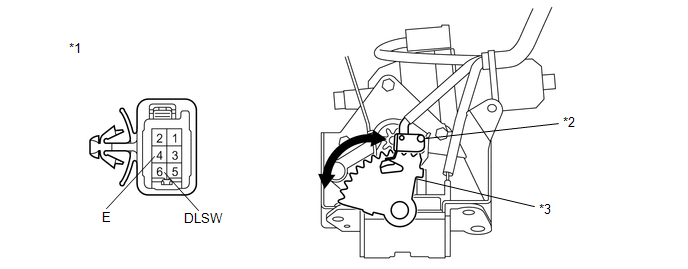
Standard Resistance:
Sector Switch|
Tester Connection |
Condition |
Specified Condition |
|---|---|---|
|
6 (DLSW) - 4 (E) |
Sector gear in neutral position (Sector switch on) |
Below 1 Ω |
|
6 (DLSW) - 4 (E) |
Sector gear not in neutral position (Sector switch off) |
10 kΩ or higher |
|
*1 |
Component without harness connected (Back Door Lock Assembly) |
*3 |
Sector Gear |
|
*2 |
Sector Switch |
- |
- |
| NG | .gif) |
REPLACE BACK DOOR LOCK ASSEMBLY |
|
.gif)
|
2. |
CHECK HARNESS AND CONNECTOR (BACK DOOR LOCK - POWER BACK DOOR ECU OR BACK DOOR CLOSER ECU) |
(a) w/ Power Back Door System
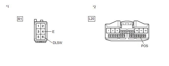
(1) Disconnect the R1 back door lock assembly connector and L20 power back door ECU connector.
(2) Measure the resistance according to the value(s) in the table below.
Standard Resistance:
|
Tester Connection |
Condition |
Specified Condition |
|---|---|---|
|
R1-6 (DLSW) - L20-24 (POS) |
Always |
Below 1 Ω |
|
R1-4 (E) - Body ground |
Always |
Below 1 Ω |
|
R1-6 (DLSW) - Body ground |
Always |
10 kΩ or higher |
|
*1 |
Front view of wire harness connector (to Back Door Lock) |
|
*2 |
Front view of wire harness connector (to Power Back Door ECU) |
|
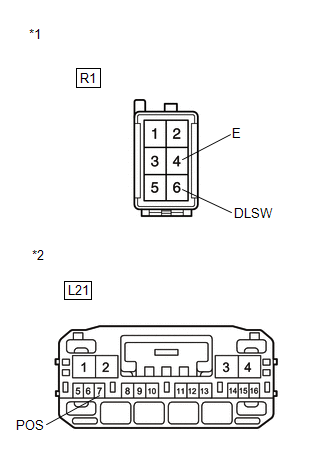
(b) w/o Power Back Door System (1) Disconnect the R1 back door lock assembly connector and L21 back door closer ECU connector. (2) Measure the resistance according to the value(s) in the table below. Standard Resistance:
|
|
|
Result |
Proceed to |
|---|---|
|
NG |
A |
|
OK (w/ Power Back Door System) |
B |
|
OK (w/o Power Back Door System) |
C |
| A | |
REPAIR OR REPLACE HARNESS OR CONNECTOR |
| B | |
REPLACE POWER BACK DOOR ECU (POWER BACK DOOR MOTOR UNIT) |
| C | |
REPLACE BACK DOOR CLOSER ECU (MULTIPLEX NETWORK DOOR ECU) |
 Diagnostic Trouble Code Chart
DIAGNOSTIC TROUBLE CODE CHART
HINT:
If a trouble code is displayed during the DTC check, inspect the trouble areas
listed for that code. For details of the code, refer to the following "See p ...
 Back Door cannot be Opened
DESCRIPTION
When the back door cannot be opened, one of the following may be malfunctioning:
1) power back door ECU (power back door motor unit)*1 or back door closer ECU (multiplex
network door ...
Other materials about Toyota Venza:
Passenger Airbag ON/OFF Indicator Circuit Malfunction (B1660/43)
DESCRIPTION
The passenger airbag ON/OFF indicator circuit consists of the center airbag sensor
assembly and accessory meter assembly (passenger airbag ON/OFF indicator).
The passenger airbag ON/OFF indicator indicates the operation condition of the
front ...
Customize Parameters
CUSTOMIZE PARAMETERS
1. CUSTOMIZE METER / GAUGE SYSTEM
(a) Customizing with the Techstream
(1) Connect the Techstream to the DLC3.
(2) Turn the ignition switch to ON.
(3) Turn the Techstream on.
(4) Enter the following menus: Customize Setting / Warning. ...
On-vehicle Inspection
ON-VEHICLE INSPECTION
PROCEDURE
1. INSPECT FLUID LEVEL
(a) Check the fluid level.
Text in Illustration
*1
MAX Line
*2
MIN Line
HINT:
If brake ...

0.1525