Toyota Venza: Installation
INSTALLATION
CAUTION / NOTICE / HINT
HINT:
- Use the same procedure for the RH side and LH side.
- The procedure listed below is for the LH side.
PROCEDURE
1. INSTALL FRONT AIRBAG SENSOR
(a) Check that the ignition switch is off.
(b) Check that the cable is disconnected from the negative (-) battery terminal.
CAUTION:
Wait at least 90 seconds after disconnecting the cable from the negative (-) battery terminal to disable the SRS system.
|
(c) Insert the pin (stopper) into the body hole. Text in Illustration
|
|
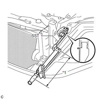
(d) Using SST, install the front airbag sensor with the bolt.
SST: 09961-00950
Torque:
Specified tightening torque :
9.0 N·m {92 kgf·cm, 80 in·lbf}
NOTICE:
- This torque value is effective when SST is parallel to the torque wrench.
- If the front airbag sensor has been dropped, or there are any cracks, dents or other defects in the case or connector, replace it with a new one.
- When installing the front airbag sensor, be careful that the SRS wiring does not interfere with or is not pinched between other parts.
- Make sure that the pin (stopper) is securely inserted into the body hole.
- Tighten the bolt while holding the front airbag sensor because the front airbag sensor pin (stopper) is easily damaged.
HINT:
- Calculate the torque wrench reading when changing the fulcrum length
of the torque wrench (See page
.gif) ).
).
- When using SST (fulcrum length of 150 mm (5.91 in.)) + torque wrench
(fulcrum length of 250 mm (9.84 in.)):
5.6 N*m (57 kgf*cm, 50 in.*lbf)
(e) Connect the connector to the front airbag sensor.
NOTICE:
When connecting the airbag connector, take care not to damage the airbag wire harness.
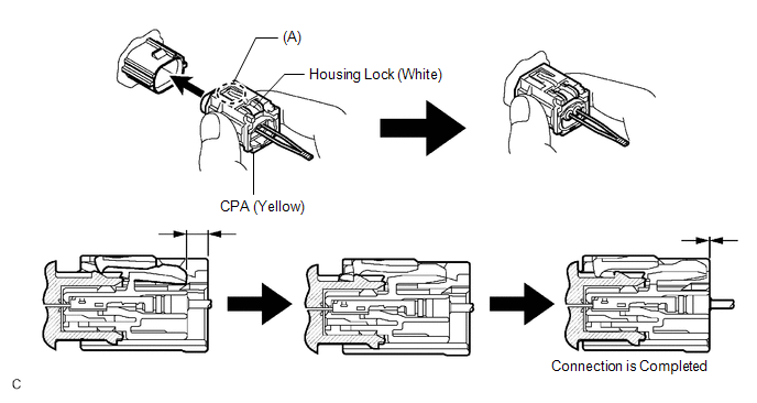
(1) Before connecting the connector, check that the position of the white housing lock is correct as shown in the illustration.
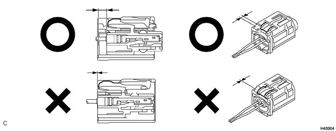
(2) Be sure to engage the connectors until they are locked (When locking, make sure that a click sound can be heard).
HINT:
When engaged, the white housing lock will slide. Be sure not to hold the white housing lock and part (A), as it may result in an insecure fit.
(f) Check that there is no looseness in the installation parts of the front airbag sensor.
|
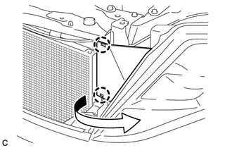
(g) Install the radiator side deflector LH with the 2 claws as shown in the illustration. |
|
2. INSTALL RADIATOR GRILLE
3. INSTALL COOL AIR INTAKE DUCT SEAL
4. CONNECT CABLE TO NEGATIVE BATTERY TERMINAL
NOTICE:
When disconnecting the cable, some systems need to be initialized after the cable
is reconnected (See page ).
5. PERFORM DIAGNOSTIC SYSTEM CHECK
(a) Perform a diagnostic system check (See page
).
6. INSPECT SRS WARNING LIGHT
(a) Inspect the SRS warning light (See page
).
 Removal
REMOVAL
CAUTION / NOTICE / HINT
HINT:
Use the same procedure for the RH side and LH side.
The procedure listed below is for the LH side.
PROCEDURE
1. PRECAUTION
CAUTION:
Be su ...

Other materials about Toyota Venza:
Screen Flicker or Color Distortion
PROCEDURE
1.
CHECK DISPLAY SETTING
(a) Reset display settings (contrast, brightness) and check that the screen appears
normal.
OK:
The display returns to normal.
OK
END
NG
...
On-vehicle Inspection
ON-VEHICLE INSPECTION
PROCEDURE
1. INSPECT ENGINE COOLANT
See page
2. INSPECT ENGINE OIL
See page
3. INSPECT BATTERY
See page
4. INSPECT AIR CLEANER FILTER ELEMENT SUB-ASSEMBLY
(a) Remove the air cleaner filter element sub-assembly.
(b) Visuall ...
Operation Check
OPERATION CHECK
1. CHECK PANEL & STEERING SWITCH
HINT:
The radio and display receiver assembly panel switches and steering
switches are checked in the following procedure.
Illustrations may differ from the actual vehicle screen depending ...

0.1254