Toyota Venza: Removal
REMOVAL
PROCEDURE
1. PRECAUTION
CAUTION:
Be sure to read Precaution thoroughly before servicing (See page
.gif) ).
).
2. DISCONNECT CABLE FROM NEGATIVE BATTERY TERMINAL
CAUTION:
Wait at least 90 seconds after disconnecting the cable from the negative (-) battery terminal to disable the SRS system.
NOTICE:
When disconnecting the cable, some systems need to be initialized after the cable
is reconnected (See page ).
3. REMOVE FRONT DOOR SCUFF PLATE LH
4. REMOVE COWL SIDE TRIM SUB-ASSEMBLY LH
5. REMOVE LOWER NO. 1 INSTRUMENT PANEL FINISH PANEL
6. REMOVE UPPER CONSOLE PANEL SUB-ASSEMBLY (w/o Seat Heater System)
7. REMOVE UPPER CONSOLE PANEL SUB-ASSEMBLY (w/ Seat Heater System)
8. REMOVE AIR CONDITIONER CONTROL ASSEMBLY
9. REMOVE FRONT DOOR SCUFF PLATE RH
10. REMOVE COWL SIDE TRIM SUB-ASSEMBLY RH
11. REMOVE NO. 2 INSTRUMENT PANEL UNDER COVER SUB-ASSEMBLY
12. REMOVE LOWER INSTRUMENT PANEL SUB-ASSEMBLY
13. REMOVE NO. 2 CONSOLE BOX CARPET
14. REMOVE CONSOLE BOX ASSEMBLY
15. REMOVE SHIFT LEVER KNOB SUB-ASSEMBLY
16. REMOVE CONSOLE BOX SUB-ASSEMBLY
17. REMOVE CENTER AIRBAG SENSOR ASSEMBLY
(a) Check that the ignition switch is off.
(b) Check that the cable is disconnected from the negative (-) battery terminal.
CAUTION:
Wait at least 90 seconds after disconnecting the cable from the negative (-) battery terminal to disable the SRS system.
|
(c) Disconnect the connector from the center airbag sensor assembly as shown in the illustration. NOTICE: When disconnecting the airbag connector, take care not to damage the airbag wire harness. |
|
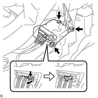
(d) Remove the 3 bolts and center airbag sensor assembly.
 On-vehicle Inspection
ON-VEHICLE INSPECTION
PROCEDURE
1. INSPECT CENTER AIRBAG SENSOR ASSEMBLY (VEHICLE NOT INVOLVED IN COLLISION)
(a) Perform a diagnostic system check (See page
).
2. INSPECT CENTER AIRBAG SENSOR AS ...
 Installation
INSTALLATION
PROCEDURE
1. INSTALL CENTER AIRBAG SENSOR ASSEMBLY
(a) Check that the ignition switch is off.
(b) Check that the cable is disconnected from the negative (-) battery terminal.
CAUTION ...
Other materials about Toyota Venza:
Window Glass Antenna Wire
On-vehicle Inspection
ON-VEHICLE INSPECTION
PROCEDURE
1. INSPECT WINDOW GLASS ANTENNA WIRE
(a) Check for continuity of the antenna.
HINT:
Check for continuity at the center of each antenna wire as shown in the
illustration.
N ...
Voice is not Recognized
PROCEDURE
1.
CHECK CONDITION
(a) Check if the system voice recognition level is low when recognizing a particular
voice.
Result
Proceed to
System voice recognition level is low only fo ...
Rear Occupant Classification Sensor LH Collision Detection (B1787)
DESCRIPTION
DTC B1787 is output when the occupant classification ECU receives a collision
detection signal sent by the rear occupant classification sensor LH if an accident
occurs.
DTC B1787 is also output when the front seat assembly RH is subjected to ...

0.1524