Toyota Venza: Removal
REMOVAL
PROCEDURE
1. REMOVE REAR SEAT HEADREST ASSEMBLY
.gif)
2. REMOVE REAR SEAT INNER TRACK BRACKET COVER
3. REMOVE REAR SEAT OUTER TRACK BRACKET COVER
4. DISCONNECT REAR SEAT NO. 2 RECLINING CONTROL CABLE SUB-ASSEMBLY
5. REMOVE REAR SEAT ASSEMBLY LH
6. REMOVE SEAT ADJUSTER COVER CAP LH
7. REMOVE REAR SEAT RECLINING RELEASE LEVER LH
8. REMOVE REAR SEAT RECLINING COVER LH
9. REMOVE REAR SEAT INNER RECLINING COVER LH
10. REMOVE REAR SEAT CUSHION COVER WITH PAD
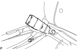
11. REMOVE REAR SEAT INNER BELT ASSEMBLY LH
|
(a) Remove the bolt and the rear seat inner belt assembly LH. |
|
 Components
COMPONENTS
ILLUSTRATION
ILLUSTRATION
...
 Installation
INSTALLATION
PROCEDURE
1. INSTALL REAR SEAT INNER BELT ASSEMBLY LH
(a) Install the rear seat inner belt assembly LH with the bolt.
Text in Illustration
*1
...
Other materials about Toyota Venza:
Removal
REMOVAL
CAUTION / NOTICE / HINT
PROCEDURE
1. PRECAUTION
NOTICE:
After turning the ignition switch off, waiting time may be required before disconnecting
the cable from the negative (-) battery terminal. Therefore, make sure to read the
disconnecting t ...
Lost Communication with ECM (U0101,U0073,U0126,U0129,U0142,U0182,U1000)
DESCRIPTION
The DTCs are stored when the CAN communication system is malfunctioning.
DTC No.
DTC Detection Condition
Trouble Area
U0101
Lost communication with ECM
CAN communication syst ...
Front Occupant Classification Sensor RH Collision Detection (B1786)
DESCRIPTION
DTC B1786 is output when the occupant classification ECU receives a collision
detection signal sent by the front occupant classification sensor RH if an accident
occurs.
DTC B1786 is also output when the front seat assembly RH is subjected to ...

0.1683