Toyota Venza: Components
COMPONENTS
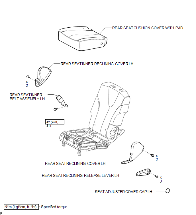
ILLUSTRATION
.png)
ILLUSTRATION

 Removal
REMOVAL
PROCEDURE
1. REMOVE REAR SEAT HEADREST ASSEMBLY
2. REMOVE REAR SEAT INNER TRACK BRACKET COVER
3. REMOVE REAR SEAT OUTER TRACK BRACKET COVER
4. DISCONNECT REAR SEAT NO. 2 RECLININ ...
Other materials about Toyota Venza:
Reassembly
REASSEMBLY
PROCEDURE
1. INSTALL FRONT DIFFERENTIAL CASE REAR TAPERED ROLLER BEARING
(a) Using SST and a press, install a new front differential case rear
tapered roller bearing (inner race) to the front differential case.
SST: 09726-36010
...
No Communication in Immobiliser System (B2796,B2798)
DESCRIPTION
These DTCs are stored if a key that does not have a transponder chip is inserted
into the ignition key cylinder or if communication between the key and the transponder
key ECU assembly is impossible.
DTC No.
DTC Detectio ...
Alarm
The system sounds the alarm and flashes lights when forcible entry is detected.
- Triggering of the alarm
The alarm is triggered in the following situations when the alarm is set.
• A locked door is unlocked or opened in any way other than by using ...

0.1962