Toyota Venza: System Description
SYSTEM DESCRIPTION
1. AUTOMATIC LIGHT CONTROL SYSTEM
When the light control switch is in the AUTO position, the automatic light control system detects ambient light levels and controls the low beam headlights, parking lights, taillights, marker lights and license plate lights.
2. LIGHT AUTO TURN-OFF SYSTEM
The light auto turn-off system is used to prevent the exterior lights from being accidentally left on (low beam headlights, high beam headlights, front fog lights, taillights, parking lights, license plate lights and marker lights).
- This system has the following functions.
|
Function |
Outline |
|---|---|
|
Driver Side Door-linked Function |
The exterior lights automatically turn off when all of the following conditions have been met:
|
|
Delay Function |
The exterior lights automatically turn off after 30 seconds when all of the following conditions have been met:
|
|
Door Control Transmitter-linked Function |
The exterior lights turn off immediately when the delay function is active and the following condition has been met:
|
3. DAYTIME RUNNING LIGHT SYSTEM (for Halogen Headlight)
The daytime running light system is designed to automatically illuminate the dimmed high beam headlights during the daytime to make the vehicle more visible to other vehicles.
- There are 2 LED type parking light circuits in each headlight. One is for a conventional low-intensity parking light that illuminates with the taillights, and the other is for the high-intensity parking light that is used for the DRL system.
- This system is controlled by the main body ECU (driver side junction block assembly) and power distributor (engine room junction block assembly). The main body ECU (driver side junction block assembly) transmits a turn on signal to the power distributor (engine room junction block assembly), which illuminates the high beam headlights using duty control.
- This system is enabled when the following conditions are met:
- Ignition switch ON
- Engine speed signal input (engine running)
- Parking brake switch off
- Light control switch is in the off, tail or AUTO position (and the low beam headlights are not turned on via the automatic light control system).
4. DAYTIME RUNNING LIGHT SYSTEM (for HID Headlight)
The daytime running light system is designed to automatically illuminate the daytime running lights during the daytime to make the vehicle more visible to other vehicles.
- This system is controlled by the main body ECU (driver side junction block assembly) and power distributor (engine room junction block assembly). The main body ECU (driver side junction block assembly) transmits a turn on signal to the power distributor (engine room junction block assembly), which illuminates the high-intensity parking lights.
- This system is enabled when the following conditions are met:
- Ignition switch ON
- Engine speed signal input (engine running)
- Parking brake switch off
- Light control switch is in the off, tail or AUTO position (and the low beam headlights are not turned on via the automatic light control system).
5. AUTOMATIC HIGH BEAM SYSTEM
(a) General
The automatic high beam system enhances the illumination of the area to the front of the vehicle to improve visibility for the driver. It works by detecting light from the front using the camera built into the inner rear view mirror assembly and turning the high beam headlights of the headlights on or off automatically.
(b) Function of Main Components
|
Component |
Outline |
|---|---|
|
Automatic High Beam Sensor (Inner Rear View Mirror Assembly) |
Determines when to turn the high beam headlights on and off after identifying the lights of oncoming vehicles, preceding vehicles and other lights from the picture information of its camera sensor. Then, it sends high beam request signals to the AFS ECU (headlight swivel ECU assembly) via LIN. |
|
AFS ECU (Headlight Swivel ECU Assembly) |
Acts as the gateway between the automatic high beam sensor (inner rear view mirror assembly) which uses LIN communication and the CAN No. 2 bus. In addition, it stores Diagnostic Trouble Codes (DTCs) if an automatic high beam sensor (inner rear view mirror assembly) malfunction occurs. HINT: Even though the vehicle is not equipped with AFS, an AFS ECU (headlight swivel ECU assembly) is provided. |
|
Power Management Control ECU Assembly |
Performs the gateway function between the No. 1 bus and No. 2 bus. |
|
Steering Angle Sensor |
Outputs the steering angle information to the AFS ECU (headlight swivel ECU assembly). |
|
Skid Control ECU |
Outputs the information about the speed of the right front wheel . This information is used by the automatic high beam sensor (inner rear view mirror assembly) to turn the high beam headlights on and off. |
|
ECM |
Outputs a signal to indicate that the shift lever is in R. Based on this signal, the automatic high beam sensor (inner rear view mirror assembly) turns the high beam headlights off. |
|
Combination Meter Assembly |
Displays automatic high beam indicator light when it receives illuminate or blink request signals from the main body ECU (driver side junction block assembly). HINT:
|
|
Main Body ECU (Driver Side Junction Block Assembly) |
|
|
Power Distributor (Engine Room Junction Block Assembly) |
Performs duty control for the high beam bulbs based on drive request signals that are received from the main body ECU (driver side junction block assembly). |
(c) Basic Function
(1) When all of the following conditions are met, the automatic high beam system is activated and the automatic high beam indicator light turns on:
- The ignition switch is ON.
- The light control switch is in the AUTO position and the low beam headlights are on.
- The dimmer switch is in the high position.
(2) When the following conditions are met, the high beam headlights automatically turn on after a short delay:
- Vehicle speed is more than approximately 20 mph (32 km/h).
- The area in front of the vehicle is dark.
- There are no oncoming vehicles with headlights on.
- There are no preceding vehicles with taillights on.
- There are few streetlights along the street ahead.
(3) When any of the following conditions are met, the high beam headlights automatically turn off after a short delay:
- Vehicle speed is less than 20 mph (32 km/h).
- The level of ambient light is higher than a specified threshold.
- There are oncoming vehicles with headlights on.
- There are preceding vehicles with taillights on.
- There are several streetlights along the street ahead.
(4) When any of the following conditions are met, the automatic high beam system will be canceled and the indicator light will turn off.
- The ignition switch is turned off.
- The light control switch is turned to any position except the AUTO position.
- The light control switch is in the AUTO position, however the low beam headlights are not on.
- The dimmer switch is moved to the low position.
HINT:
It is possible to manually switch between the high beam headlights and low beam headlights using either of the following operations:
- Turn the light control switch from the auto position to the head position. In this case, the high beam headlights turn on according to the dimmer switch high position. To change to the low beam headlights, move the dimmer switch to the low position.
- Move the dimmer switch from the high position to the low position. In this case, the low beam headlights turn on according to the dimmer switch position.
HINT:
The automatic high beam system monitors the area in front of the vehicle using the camera built into the inner rear view mirror assembly and makes a judgment to turn on the high beam headlights when the surrounding area is dark (there are no headlights from oncoming vehicles and no taillights from vehicles in front). High beam control limitations:
- When the surrounding area is not dark enough, the low beam headlights will remain on even if the headlights are turned on by the automatic light control system and the automatic high beam indicator light on the combination meter assembly illuminates. (The light level sufficient to turn the auto low beam headlights on is not the same as the light level required to automatically illuminate the high beam headlights.)
- When an oncoming vehicle suddenly appears at a sharp curve or a vehicle crosses the path of the vehicle, the high beam headlights may remain on.
- When the fog lights of an oncoming vehicle are detected, the high beam headlights may be turned off.
- The timing of the high beam headlights turning on and off may differ depending on the brightness of headlights or fog lights from oncoming vehicles or the taillights of preceding vehicles.
- The timing of the high beam headlights turning on and off may differ between normal conditions (good weather) and when driving on wet, frozen or snowy roads.
- The timing of the high beam headlights turning on and off may differ depending on the number of occupants and amount of cargo present.
- On some occasions, the high beam headlights and low beam headlights may change unexpectedly.
HINT:
The camera built into the inner rear view mirror assembly continually monitors the light level in the area to the front of the vehicle. There is a delay in turning on the high beam headlights. Even when there is no ambient light, the high beam headlights will not turn on immediately. The delay will vary depend on the situation.
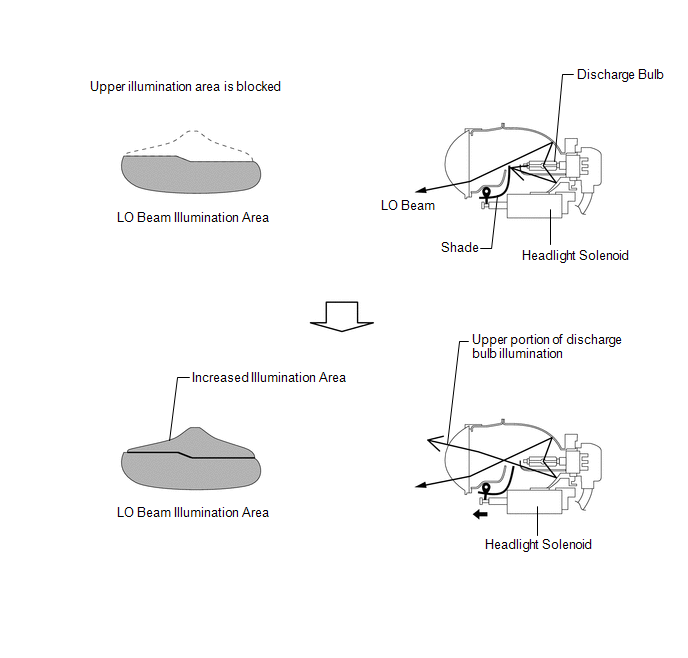
6. BI-FUNCTION
(a) The models with HID (High Intensity Discharge) headlights have a Bi-function. This Bi-function increases the upper illumination area of the discharge bulb (low/high beam) when the high beam is turned on.
- If the low beam is selected, the upper illumination area of the discharge bulb is blocked by a shade and only the lower illumination area is used. If the high beam is selected, the headlight solenoid slides the shutter (shade) down to allow use of the upper illumination area, thus increasing the illumination area and improving visibility when the high beam is on.
- This function is activated by the front controller. The front controller receives a high beam turn ON signal from the main body ECU RH and activates the headlight solenoid built into the headlight unit to slide the shade down.
7. HID HEADLIGHT SYSTEM
The High Intensity Discharge (HID) headlight system uses a discharge bulb as its light source for the low beam. Discharge bulbs are superior to halogen bulbs.
- Discharge bulbs have the following features:
- The light emitted by the bulb is close in color to sunlight. The light shines further forward and over a broader area, increasing the area visible to the driver.
- Less power is consumed.
- This system consists of the discharge bulbs and light control ECUs.
- The light control ECU transforms voltage that is input from the battery to high voltage of up to 30000 V and applies it to the discharge bulbs in order to illuminate them.
8. AUTOMATIC HEADLIGHT BEAM LEVEL CONTROL SYSTEM
(a) General
- This system maintains the low beam headlights at a constant level while the vehicle is stopping.
- This system is controlled by the headlight leveling ECU assembly. The headlight leveling ECU assembly detects the vehicle posture via the rear height control sensor sub-assembly RH, and detects the vehicle speed via the combination meter assembly. The headlight leveling ECU assembly controls each headlight leveling motor (headlight unit) based on these pieces of information in order to change the headlight reflector angle.
NOTICE:
- Initialize the rear height control sensor sub-assembly RH signal after the vehicle height changes due to replacement of the suspension or after operations as reinstallation or replacement of the rear height control sensor sub-assembly RH.
- When the headlight leveling ECU assembly is replaced, initialization is also necessary.
(b) Function of Main Components
|
Component |
Outline |
|---|---|
|
Rear Height Control Sensor Sub-assembly RH |
Detects vehicle height. |
|
Combination Meter Assembly |
|
|
Headlight Leveling Motor (Headlight Unit) |
Based on the signals received from the headlight leveling ECU assembly, each motor moves the reflector in the headlight to vary its low beam. |
|
Headlight Leveling ECU Assembly |
|
9. DOOR MIRROR FOOT LIGHT SYSTEM
(a) General
- The door mirror foot light control consists primarily of the fade-in/fade-out function and timer illumination function.
- This control is controlled by the main body ECU (driver side junction block assembly).
(b) The door mirror foot light system has the following control functions:
|
Function |
Outline |
|---|---|
|
Actuation Area-linked* |
When all of the following conditions are met, the lights that operate turn on:
|
|
When the following condition is met, the lights that operate turn off:
|
|
|
Door Unlock-linked |
When all of the following conditions are met, the lights that operate turn on:
|
|
Door Lock-linked |
When either of the following conditions is met, the lights that operate turn off:
|
|
Delay |
When approximately 15 seconds elapse after any of the following conditions are met, the lights that operate turn off:
|
|
When either of the following conditions is met while the delay function is operating, the lights that operate remain on for approximately 15 seconds longer:
|
|
|
Shift Lever Position-linked |
When both of the following conditions are met, the lights that operate turn off:
|
- *: w/ Smart Key System
 Precaution
PRECAUTION
NOTICE:
When disconnecting the cable from the negative (-) battery terminal, initialize
the following systems after the cable is reconnected.
System Name
See Proc ...
 System Diagram
SYSTEM DIAGRAM
1. AUTOMATIC LIGHT CONTROL SYSTEM
2. LIGHT AUTO TURN-OFF SYSTEM
Communication Table
Transmitter
Receiver
Line
Data Name
...
Other materials about Toyota Venza:
Rear seats
Seatback angle adjustment lever
Pull up the lever until the lock is completely released.
Folding down the rear seatbacks
- Before folding down the rear seatbacks
Stow the seat belt buckles and lower the head restraints to the lowest position.
...
Precaution
PRECAUTION
NOTICE:
When disconnecting the cable from the negative (-) battery terminal, initialize
the following systems after the cable is reconnected.
System Name
See Procedure
Back Door Closer System
...
Registration
REGISTRATION
PROCEDURE
1. REGISTER TRANSMITTER CODE
HINT:
The vehicles garage door opener system records transmitter codes for
systems such as garage doors, gates, door locks, home lighting systems,
security systems or other transmitter-cod ...

0.1382